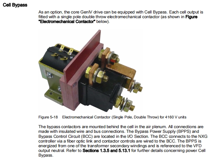


ROBICON Perfect Harmony GenIV Cell Bypass Contactor A5E50124596, A5E40727031; A5E02634363, A5E32187356
ROBICON Perfect Harmony GenIV Cell Bypass Contactor A5E50124596, A5E40727031; A5E02634363, A5E32187356
ROBICON Perfect Harmony GenIV Cell Bypass Contactor A5E50124596, A5E40727031; A5E02634363, A5E32187356
ROBICON Perfect Harmony GenIV Product User Manual Type 6SR41
Harmony VFD Family Features
The Harmony VFD families consist of four core design configurations, where they are
functionally identical and share a common controller. These four design configurations are
targeted at distinct output power configurations with little overlap between the frame sizes.
These drive families are summarized as follows:
Note
The following ratings are subject to change.
GenIV:
(Refer to Table 4-1 for full GenIV product range)
200 to 5600 Hp (150 - 4100 kW)
● 2.3 to 11 kV Output
● 2.4 to 13.8 kVAC 50/60 Hz Input
● Air Cooled
● Power Cell Ratings
– 750 Volts
– 40, 70, 100, 140, 200 or 260 Arms
GenIIIe:
● 3000 to 9000 Hp (2.25 - 6.75 MW)
● 2.3 to 7.2 kV Output
● 2.4 to 13.8 kVAC 50/60 Hz Input
● Air Cooled
● Power Cell Ratings:
– 690 Volts
– 315, 375, 500, or 660 Arms
WCIII:
● 4000 to 10000 Hp (3 MW - 14.2 MW)
● 2.3 to 8.0 kV Output
● 2.4 to 13.8 kVAC 50/60 Hz Input
● Water Cooled
● Power Cell Ratings:
– 750 Volts
– 880 or 1250 Arms
HV:
● 10000 to 40000 Hp (7.5 MW to 30 MW)
● 7.2 to 13.8 kV Output
● 2.4 to 13.8 kVAC 50/60 Hz Input
● Water Cooled
● Power Cells
– 1375 Volts
– 500, 800, or 1400 Arms
Evolution
Historic Milestones:
1994: World’s 1st fully integrated voltage source inverter (VSI) medium voltage motor
drive using IGBTs that meet IEEE 519 for input current distortion and NEMA/IEC
for motor HVF (without using output step-up transformers or line/load filters).
1995: 1st IGBT-based 6.6 kV drive without an output transformer.
1996: 1st IGBT-based drive above 10000 Hp (7500 kW).
1998: Introduction of ProToPSTM and 500th Perfect Harmony drive installed.
1999: Introduction of process-transparent cell bypass ("fast bypass") capability and
neutral point shift.
2000: 1st VSI drive to operate a medium voltage synchronous motor.
2001: 1000th Perfect harmony drive installed.
2002: 1500th Perfect Harmony drive installed.
2003: 1st High Voltage 13.8 kV drive capable of operating motors from 4000 to
90000 Hp connected directly to 13.8 kV source.
2004: Built largest PWM drive, 80000 Hp.
2006: Introduction of smallest footprint medium voltage VFD, GenIV "MicroHarmony".
GenIV Specifications 4
4.1 System Specifications
Parameter Rating
Input Line Voltage 2.4, 3.0, 3.3, 4.16, 4.8, 6.0, 6.3, 6.6, 6.9, 7.2, 8.4, 10, 11, 12, 12.47, 13.2, or 13.8kV; 3 phase;
±10% / -5%
Input Frequency 50 or 60 Hz ±5%
Input Power Factor > 0.95 above 10% load
Input Harmonics <= 5% TDD with ambient THDv <= 2%
Copper Wound Transformer: 98% Transformer, 99% Converter, > 96,5% Total VFD Efficiency
Aluminium Wound Transformer: 97,5% Transformer, 99% Converter, > 96% Total VFD
Output Horsepower,
Frame Sizes
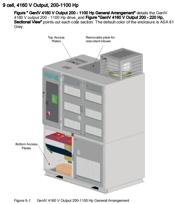
200-1100 (9 Cell - Size 1), 800-2250 (9 Cell - Size 2),
300 - 3500 (15 Cell), 600-6000 (24 Cell)
9 Cell 15 Cell 24 Cell
2300 V 6000 V 10000 V
3000 V 6600 V 11000 V
3300 V
4000 V
4160 V
Output Voltage
Output HVF < 0.03
Output dv/dt < 3000 V/µS
Output Current 40, 70, 100, 140 A, 200 A, 260 A Cell Frame Sizes
Overload Capacity 150% 1 minute / 10 minute (Ambient temperature <40°C)
Output Frequency & Drift1 0.5 - 330 Hz, ± 0.5%
Output Torque 10 - 167 Hz rated torque (2 Quadrant)
Design Life 20 years
Auxiliary Voltage 380 - 400 - 415V, 50 Hz; 460 - 480V, 60 Hz; 3 phase2)
Enclosure Type NEMA 1 Ventilated
Degree of Protection IP 31
Ambient Temperature 0 - 40 °C (max. 50 °C, derating starts from 40 °C on)
Humidity 95% non-condensing
Altitude 0 - 3300 ft. without derating
Cooling Ventilated, forced air-cooled with integrated fans
1) For high speed projects (> 300 Hz), consult Siemens concerning trade sanctions
2) Consult factory for availability of auxiliary voltages other than shown
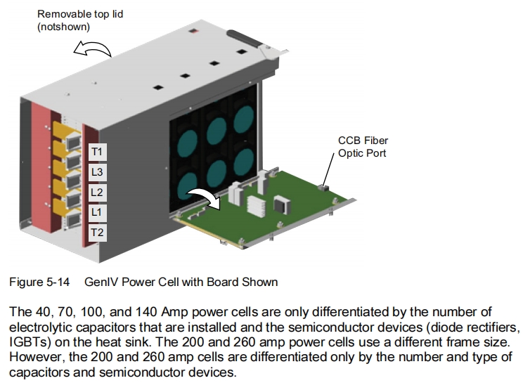
Power Cell Specifications
Cell Frame FRAME1 FRAME2
040 070 100 140 200 260
Output Nameplate
Current
40 A 70 A 100 A 140 A 200 A 260 A
Input Voltage 750 V ± 10%, 3 phase, 50/60 Hz
Input Current 28 A 48 A 73 A 96 A 140 A 182 A
Overload Capacity (see
Note)
(* Ambient <40°C)
CL-1: 110% of nameplate 1 minute/10 minutes
CL-2: 150% of nameplate 1 minute/10 minutes
CL-3: 200% of nameplate 3 seconds/10 minutes
Losses % 1.3 1.2 1.1 1.0 1.2 1.2
Discharge to 50 VDC,
minutes.
0.84 1.68 2.53 3.37 2.53 3.37
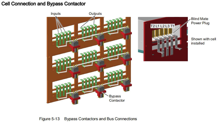
Electrical Connections Rear access blind connection via power plugs
Weight (lbs.) 52 57.5 63 68.5 63 68.5
Envelope Width 13.42"
Envelope Depth
Envelope Height
21.83"
9.67"
Forced Air Cooling > 180 CFM (225-250 typical) 300 CFM (300-350 typical)
Note
At ambient temperatures ranging from 40 to 45°C, the 140 A cell frame is limited to 150%
1 minute/10 minutes overload with a 130 Amp continuous rating
GenIV Core Configurations:
Cells in Drive
(without Redundancy)
Output Voltage
Available L-L
(with O-M)
Hp Range Power Cell Types (Continuous
Current Rating)
9 4000 V (4160 V) 200-1100 40, 70, 100, 140
9 4000 V (4160 V) 800-2250 40, 70, 100, 140, 200, 260
15 6600 V (6600 V) 300-3500 40, 70, 100, 140, 200, 260
24 10000 V (11000 V) 600-6000 40, 70, 100, 140, 200, 260
Previous : M6R42020CF415BH0-Z, SIEMENS A5E02260655, CCB A1A10000432.72M, GCB A1A10000428.05M, FF300R17KE3, A1A097068, A5E02634309, A1A10000484.00, A5E01649325, A1A0100505, A1A0100118
Next : Innomotics Siemens NXGpro DCR 9-12 Cell A5E33032452, NXGpro DCR 15 Cell A5E37764609, NXGpro DCR 18 Cell A5E33032455, NXGpro DCR 21 Cell A5E37764770, NXGpro DCR 24 Cell A5E33032458, NXGpro CF Card A5E35236834


 Copy product links
 Long by picture save/share
ROBICON Perfect Harmony GenIV Cell Bypass Contactor A5E50124596, A5E40727031; A5E02634363, A5E32187356
INQUIRY


Add Successfully
We are the world's leading supplier of spare parts for medium voltage drives of various brands

点击右上角
分享给朋友吧
GET IN TOUCH

East Sun Industrial Centre, No 16 Shing Yip Street Kl, Hongkong

Call us : +852 5261 7322

Email us : [email protected]
SITEMAP
BUSINESS HOURS
Monday to Friday : 9 am to 6 pm
Saturday : 9 am to 12 am
Sunday : Closed Support Hours in 24/7 Everyday
DISCLAIMER:
We are not an authorized distributor, reseller or representative of the following products presented on this website. All Product names and logos throughout this site are trademarks of their respective holders. Use of them DOES NOT imply any affiliation with or endorsement by them.
© 2020 robiconperfectharmony.com site . All rights reserved Site Map
