

Siemens Robicon Perfect Harmony GH180 NXG NXGpro NXG controller Tool Suite Latest Version 6.4.1
Siemens Robicon Perfect Harmony GH180 NXG NXGpro NXG controller Tool Suite Latest Version 6.4.1
Cell Control board faulted
Dears,
We use RobiconHARMONY DRIVE GEN III/Eon 3.2 MW inductor motor with pump load.
The drive is faulted and we get ''C3 control power '' fault.
I think the problem must be oncell control boards otherwise the fault whould not change from C3 to B3 when we exchange the cell control boards.
Now, I don't have any spare cell control board. Is there any way to fix or to bypass this fault ?
Kind regards
If the cell control board is confirmed as faulty it needs to be replaced. The faulty board can be repaired and put back into service after repair and testing.
Current Consumption of DeviceNet Interface
Hi all,
I can't seem to find this information anywhere, but I am designing a devicenet network which is close to exceeding its safe, designed current limit. (an arbitrarily assigned value which is 20% less than the Devicenet power supply)
As such, I would like to know what the current consumption is of the devicenet interface module supplied in a Perfect Harmony inverter.
Does anyone have that current value handy?
Thanks in advance,
Berm
Hello Berminator,
I dont have the exact values either, but from my experience a devicenet interface can be calculated with 5 W. That should be pretty close to any, but still on save side.
You can then calculate current consumption as 5W/Supply voltage.
regards
A1A10000432.02M - I am looking for help
Tom whom it maybe concerned,
In my pump station, we have 2 x 1.8MW Robincon inverters which are facing with problem. One of them returns error that the cell control board is fault!
The PN of control board is A1A10000432.02M and now I want to replace the new cell control board.
If you can supply the such spare part or you know the supplier, please let me know!
Hi,
Please use the following info to contact our service center for spare parts. I would not recommend just replacing the cell control board. Please contact our tech support to troubleshoot your drive issue before replacing cell control board.
thanks
Sathiy
Many thanks for your support!
Many thanks Sathiy for your suggestion,
I have contacted with Siemens technical support agent, but the response did not make me be sastisfied,
Maybe I have to wait for long time in order to get the support!
Best regards,
Dears,
What is the margins for NXG power supply 24. 15, and 5 VDC outputs.
Thanks
SM Field Current reference
We have pump set with Sync motor and Robicon Gen IV. Siemens Robicon GH180 Gen IV gives the analog reference for SM field current, but there are no parameters in ToolSuite which provides the scaling of this signal. We adjusted the scale of Exiter to nominal value of motor. It seems that motor works good and it get needed exitation, but how Gen IV understand that this reference is needed?
So question is: How Gen IV calculates the scaling of Fiels Current ? Does it use the nominal parameteres of the Motor? or it use Iq and Id values?
Thanx for Your answer.
I saw this circuit, but it doesnt include needed information.
I need tocorrelate field scaling between Siemens Robicon GH180 GEN IV and External Exciter.
I have adjusted Analog Output #2 for SM field current reference and I think that logically It must be adjustments for scaling - 4mA corresponds for low level field current and 20mA corresponds for high level of field current. And it seems like that this adjustements does not exist and Gen IV calculates the Field Current reference withonly known to it scale.
With best regards
Hi boyn84,
I have used the procedure below to calibrate the exciter shown in the attached pdf. 20mA = motor rated current.
3PCI Exciter Calibration
Turn the gain and the current limit all the way up. This is clockwise, being very careful not to go past the stop on the potentiometer. You will feel a very slight resistance when you have gone too far, they are 20 turn pots.
Inject a 4mA signal with the exciter enabled and the output connected. Turn the bias pot counterclockwise until you are biased on (output is visible with a current clamp on a Fluke 43B or similar). Then go counterclockwise until it is just biased off.
Now begin to increase the signal in 4mA increments until you are near or at motor rated exciter current. Do not just go to 20mA and hope for the best, you could damage the 3PCI or the exciter windings, if you exceed motor rated step down by 4mA and begin turning the gain counterclockwise until the output decreases. Then step up 4mA and repeat this process until the output is at motor rated plus 5 amps.
Adjust the current limit counterclockwise until you see a reduction in the output. At this point turn clockwise until the reduction is gone.
Now reduce the gain pot until the exciter output is at motor rated.
Immediately step down to 4mA, you will notice that the output is still biased on. Begin reducing the bias (CCW) until the output just shuts off.
Now step up to 20mA, the gain will need to be increased slightly as the bias and gain are codependent settings. Once you are again at motor rated, immediately step down and verify that there is no output with a 4mA input.
Step up the input in 0.1mA increments, the exciter should be biased on at approximately 4.3mA.
Important notes: this activity generates a lot of heat in the motor, please review this procedure thoroughly and make haste in your calibration efforts. Again step up the current injection, do not just jump to 20mA when setting the gain. The lower the gain setting, the sooner the bias will turn the exciter on. That said, there are many points that can achieve the same end result (output) although if not calibrated properly the response will be very sluggish relative to the input.
Hi,
4-20mA signal can be calibrated withmotor speed signal, and then youcan change the I/O for other signal. it will be right.
VFD will maitain the powerfactor equal 1.
SINAMICS Perfect Harmony GH180 is not work "Down Transfer" Operation for Induction Motors
Dear Pro.
There is my problem: Robicon Perfect Harmony is not work "Down Transfer" Operation for Induction Motors.
I use Perfect Harmony (VFD) with the function "Synchronous Transfer" to "soft start" and "soft stop" for one induction motor 1.8MW. Synchronous Transfer Operation is controlled by one PLC S7-1200 via Wago I/O system.
In firmware for SINAMICS Perfect Harmony GH150, I use one counter to start VFD:
Counter03(1) = TempFlag02_O * DE_RunningEnalbe_DI * ReadytoRun_I * DE_VFCRunRequest_DI;
where: TempFlag02_O : signal reported VFD no errors.
DE_RunningEnalbe_DI: signal allowing VFD run.
ReadytoRun_I: system flag.
DE_VFCRunRequest_DI: signal start VFD.
In Up transfer operation, VFD works well.
But in Down transfer operation:
- PLC provides the VFD with the acknowledge from the line contactor.
- PLC issues a "down transfer request"
- PLC issues a "runrequest" to the VFD.
VFD does not enter "DOWN_TRANSFER" state, which is still in "IDLE" state.
Someone can tell me what I was wrong and what I can be done to implement Down Transfer.
Thank you very much. Sorry for my english is very bad!
PS: this is Parameter Dump File of VFD
Set the Speed Fwd Max Limit1 (2080) to at least 105%.
Do you have a copy of NXG Control Manual A1AD19001588?
Thank you for Your answer!
I have a NXG Control Manual A1AD19001588.
In my VFD:
- Spinning load mode = Forward (parameter 2430)
- Speed fwd max limit 1 = 100.0% (parameter 2080)
I will follow your advice.
I have read topic:/tf/WW/en/Posts/114138
Different boyn84, inDown transfer operation, my VFD does not enter "DOWN_TRANSFER" state, which is still in "IDLE" state.
Best Regards.
Use the Siemens Perfect Harmony GH180 NXG debug tool to monitor the system program flags. With refering to section 5.16.4 in the NXG control manual you should be able to find the condition which is stopping the drive from coming out of the idle state.
Check "DownTransferRequest_O" and "DownTransferPermit_I".
Thank you.
I have installed VFD follow theNXG Control Manual A1AD19001588 (section 5.16.4).
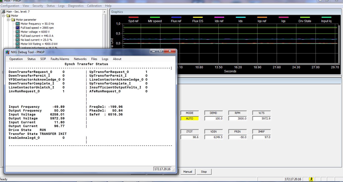
Ihave beenmonitor the system program flags:
- LineContactorAcknowledge_O = 1
-DownTransferRequest_O = 1
-VFCRunRequest_DI = 1 (Digital input - WAGO module)
But invRunRequest_O = 0; Drive State : IDLE; Transfer State: TRANSFER INIT.
Best Regards.
Double check the following steps from the manual. Ensure there is at least 250ms between sending subsequent signals.Ensure the PLC is closing the VFD contactor when DownTransferPermit_I = 1 as per step 7.
“Down” Transfer (from Line to VFD Control)
1. The Down Transfer process (refer to Figure 5-26) consists of the following steps. The line contactor isassumed to be closed at the beginning of this procedure.
2. The PLC switches to the correct motor parameters in the VFD through the System Program, if required.
(This step is possible in Version 2.3 or higher of NXG software.)
3. The PLC provides the VFD with the acknowledge from the line contactor [LineContactorAcknowledge_O].
4. The PLC issues a “down transfer request” [DownTransferRequest_O].
5. The PLC issues a “run request” [RunRequest_O] to the drive.
6. The VFD issues a “transfer permit” command [DownTransferPermit_I] to the PLC if the drive can providesufficient voltage to match the line. The VFD then enters the Down Transfer drive state.
7. The PLC closes the VFD contactor. When the VFD contactor is closed, the PLC sends a signal to the VFDindicating the VFD contactor (e.g., V1) is closed [VFDContactorAcknowledge_O]. VFD then waits fiveseconds for stabilization of the PLL.
8. The VFD locks-in to the line frequency and builds torque current to 25%; it then issues the “line contactorunlatch” signal [LineContactorUnlatch_I] to the PLC.
9. The PLC verifies that the VFD has not faulted.
10. The line contactor (e.g., L1) is opened by the PLC. When the line contactor is opened, the signal[LineContactorAcknowledge_O] is cleared.
11. The VFD signals the PLC “down transfer complete” [DownTransferComplete_I].
12. The PLC removes the “down transfer request” [DownTransferRequest_O], but maintains the “run request.”Note: Removing the DownTransferRequest_O flag resets the DownTransferComplete_I flag. If theDownTransferComplete_I flag is required for other logic, it must be latched.
13. The VFD clears the [DownTransfer Permit_I] and the Line [ContactorUnlatch_I] flags, exits the DownTransfer Drive state, and enters the Drive Run state.
14. The VFD follows the process setpoint from the PLC.
Thanks for your reply.
I have found cause of VFD not switch from IDLE State to the DOWN_TRANSFER State, the cause of this is not due to the firmware of the VFD as well as the settings. This occurs because the control system has one agent protection activities to prevent the VFD running while motor is running directly from the power grid. I have resolved this problem, but currently, I encountered the following problem: the DOWN_TRANSFER implementation failed.
I've always used the Robicon Perfect Harmony GH180 NXG debug tool to monitor the system program flags.
I've Enabled Spinning Load by setting Spinning Load Mode (2430) to Forward.
At first try, I've set the Speed Fwd Max Limit1 (2080) to 105%.
Drive State: DOWN TRANSFER
Transfer State: TRANSFER_INIT -> WAITING_FOR_FREQUENCY_LOCK -> WAITING_FOR_TORQUE_TO_BUILD. However, transfer_state remained unchanged until the error timeout (300 seconds).
At the second try (parameter 2080: 105%) (*)
Drive State: constantly shift between two states and COAST and DOWN TRANSFER
Transfer State: TRANSFER_INIT (sometimes switch to WAITING_WAITING_FOR_FREQUENCY_LOCK, then returned TRANSFER_INIT)
Next, I've set the Speed Fwd Max Limit1 (2080) to 105%. In Up transfer operation, VFD immediately corrupted and not complete the UP_TRANSFER.
Then I had to disconnect the contactor connect the VFD to DC by manual. Next, I try to Down Transfer, but the VFD status remains the same as in the 2nd attempt (*)
Then I've set the Speed Fwd Max Limit1 (2080) to 107%. In Up transfer operation VFD works well, but during Down transfer operation VFD status remains the same as in the 2nd attempt (*)
Then I also tried to set Current Level Setpoint (parameters 2450) to 20% or 25% (default: 15%), but the results remained unchanged.
Can you give advice and solutions to solve my problem.
Thank you very much.
With Best Regards.
MyAttachment:screen of NXG debug tool (Status/Advanced).
With Best Regards.
Thank you.
On the screen of SINAMICS Perfect Harmony GH180 NXG debug tool, the line-frequency: 49.93 ~ 50.13 Hz.It is a steady frequency.
I've tried increasing Speed Fwd Max Limit1 (p2080). When I've set the Speed Fwd Max Limit1 to 110%, in Up transfer operation VFD immediately corrupted and not complete the UP_TRANSFER.
When I've set the Speed Fwd Max Limit1 to 107% (or 105%), in Up transfer operation VFD works well, but in down transfer, VFD didn't work as expected.
With Best Regards.
Robicon Perfect Harmony Gen3
Taking the old PLC logic from the Siemens Robicon Perfect harmony, which is using global data through Modbus Plus Communications and writing it to function block.
My question is: Some analog values coming from the VFD, which are: Speed Feedback word 1 and word 2, Total current Feedback w1 and w2, Motor Voltage Feedback w1 and w2, and Power voltage w1 and w2. In the original canned PLC program only the first word of each value is used for scaling. Every value is divided by 8192, can you tell me why this is 8192? Are these Unsigned Integers? Any manual or reference material would be greatly appreciated.
NXG SINAMICS perfect harmony drive - humming noise from the transformer during startup
we have Siemens Robicon NXG perfect harmony drive with 3 cells in series, bypass capability.
we have isolated the drive for about 8 days and attempted to start up but it came up with loud 50hz humming noise from the transformer.
We have megger the primary windings and check cable torque settings.
The noise is still there.
We had input protection fault when the drive was turned off initially and starting up we medium voltage low fault.
Hi Alicia,
During start up the sound from built in trafo is common due to high in rush currents.
After you made MV ON, is the drive is again tripping ? or it is healthy.
If MV power is cutoff 'MV low alarm' is also common as voltage below 90% sensing causes this alarm. After MV ON, no abnormal sound shall continue.
Regards,
Vijay
Robicon CPU card battery
Hi
What is the MLFB for CPU card battery?
Thanking you in advance
Regards,
N. Vijay
Hi
I checked it during shutdown. and is PANASONIC make Type BR2032
and google pages say it can be replaced with CR2032 ?! Simple button type cell used in Calculators
Regards,
Vijay
Hello Vijay,
BR2032 is the same of CR2032, (BR) is manufacturer code
while CR2032 is IEC code
hi Ste39,
No, both are not exactly same.Some features still differ. See the attachment
But they are equivalents
Regards,
Vijay
Previous : Siemens Robicon Perfect Harmony GH180 NXG NXGpro NXG controller Tool Suite Latest Version 5.1.0.1
Next : Siemens Robicon Perfect Harmony GH180 NXG NXGpro NXG controller Tool Suite 6.4.1 GenIV GenI GenII


 Copy product links
 Long by picture save/share
INQUIRY


Add Successfully
We are the world's leading supplier of spare parts for medium voltage drives of various brands

点击右上角
分享给朋友吧
GET IN TOUCH

East Sun Industrial Centre, No 16 Shing Yip Street Kl, Hongkong

Call us : +852 5261 7322

Email us : [email protected]
SITEMAP
BUSINESS HOURS
Monday to Friday : 9 am to 6 pm
Saturday : 9 am to 12 am
Sunday : Closed Support Hours in 24/7 Everyday
DISCLAIMER:
We are not an authorized distributor, reseller or representative of the following products presented on this website. All Product names and logos throughout this site are trademarks of their respective holders. Use of them DOES NOT imply any affiliation with or endorsement by them.
© 2020 robiconperfectharmony.com site . All rights reserved Site Map
