
SINAMICS PERFECT HARMONY GH180 Air-Cooled Drives Portfolio Brazilian Factory JUNDIAI
SINAMICS PERFECT HARMONY GH180 Air-Cooled Drives Portfolio Brazilian Factory JUNDIAI
Catalog | Brazilian Edition | 2020
1
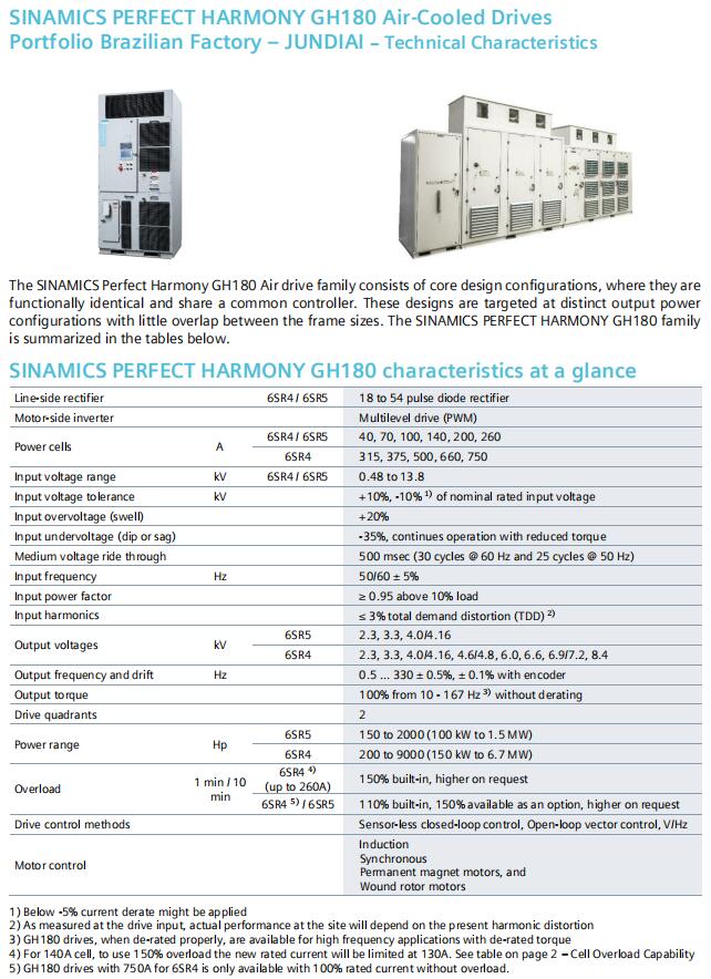
SINAMICS PERFECT HARMONY GH180 Air-Cooled Drives
Portfolio Brazilian Factory – JUNDIAI – Technical Characteristics
The SINAMICS Perfect Harmony GH180 Air drive family consists of core design configurations, where they are
functionally identical and share a common controller. These designs are targeted at distinct output power
configurations with little overlap between the frame sizes. The SINAMICS PERFECT HARMONY GH180 family
is summarized in the tables below.
SINAMICS PERFECT HARMONY GH180 characteristics at a glance
Line-side rectifier 6SR4 / 6SR5 18 to 54 pulse diode rectifier
Motor-side inverter Multilevel drive (PWM)
Power cells A
6SR4 / 6SR5 40, 70, 100, 140, 200, 260
6SR4 315, 375, 500, 660, 750
Input voltage range kV 6SR4 / 6SR5 0.48 to 13.8
Input voltage tolerance kV +10%, -10% 1) of nominal rated input voltage
Input overvoltage (swell) +20%
Input undervoltage (dip or sag) -35%, continues operation with reduced torque
Medium voltage ride through 500 msec (30 cycles @ 60 Hz and 25 cycles @ 50 Hz)
Input frequency Hz 50/60 ± 5%
Input power factor ≥ 0.95 above 10% load
Input harmonics ≤ 3% total demand distortion (TDD) 2)
Output voltages kV
6SR5 2.3, 3.3, 4.0/4.16
6SR4 2.3, 3.3, 4.0/4.16, 4.6/4.8, 6.0, 6.6, 6.9/7.2, 8.4
Output frequency and drift Hz 0.5 ... 330 ± 0.5%, ± 0.1% with encoder
Output torque 100% from 10 - 167 Hz 3) without derating
Drive quadrants 2
Power range Hp
6SR5 150 to 2000 (100 kW to 1.5 MW)
6SR4 200 to 9000 (150 kW to 6.7 MW)
Overload 1 min / 10
min
6SR4 4)
(up to 260A) 150% built-in, higher on request
6SR4 5)
/ 6SR5 110% built-in, 150% available as an option, higher on request
Drive control methods Sensor-less closed-loop control, Open-loop vector control, V/Hz
Motor control
Induction
Synchronous
Permanent magnet motors, and
Wound rotor motors
1) Below -5% current derate might be applied
2) As measured at the drive input, actual performance at the site will depend on the present harmonic distortion
3) GH180 drives, when de-rated properly, are available for high frequency applications with de-rated torque
4) For 140A cell, to use 150% overload the new rated current will be limited at 130A. See table on page 2 – Cell Overload Capability
5) GH180 drives with 750A for 6SR4 is only available with 100% rated current without overload.
Catalog | Brazilian Edition | 2020
2
SINAMICS PERFECT HARMONY GH180 Technical Data
General Technical Data
General Technical Data
Drive quadrants 2
Isolation Fiber optic cable
Rated Efficiency Cu Typical 97.0 % including transformer, 96.5% guaranteed across whole product range
Al Typical 96.5 % including transformer, 96% guaranteed across whole product range
Regulation compliances IEEE, ANSI, CE
Degree of Protection1)
6SR5 IP42 (standard)
6SR4 IP31 (standard) / IP42 (optional M42)
Altitude Ft (m) 0…3,300 (1,000) standard, Up to 14,763 (4,500) with de-rating
Sound Pressure Level at 3ft (1m) dBA 80
Power Cabling Cross Sections2)
6SR5 6SR5 6SR5 6SR4 6SR4
40-70A 100-140A 200-260A 315-375A 500-750A
Line-side, max. connectable per
phase with M10 screw
preliminary
AWG/MCM
(NEC, CEC)
1 x 350
MCM
1 x 4/0
AWG
1 x 500 MCM
2 x 2/0 AWG
2 x 500
MCM
2 x 1000
MCM
mm²
(DIN VDE) 1 x 177 1 x 10⁷ 1 X 253
2 x 67 2 x 253 2 x 507
Motor-side, max. connectable
per phase with M10 screw
preliminary
AWG/MCM
(NEC, CEC)
1 x #2
AWG
1 x 2/0
AWG
1 x 4/0
AWG
1 x 500
MCM
2 x 1000
MCM
mm²
(DIN VDE) 1 x 33 1 x 67 1x 10⁷ 2 x 507 2 x 507
PE (protective earth)
connection, max. connection
cross-section at enclosure with
M12 screw preliminary
AWG/MCM
(NEC, CEC) 2/0 AWG 2/0 AWG 2/0 AWG 2/0 AWG 1000 MCM
mm²
(DIN VDE) 67 67 67 67 507
1) According to IEC 60529
2) Maximum installable size per phase, shielded cables
Cell Overload Capability
6SR5 6SR4
Cell Rating 40 70 100 140 200 260 40 70 100 140 200 260 315 375 500 660 750
Maximum cell continuous
output current for 60s
(Imax,60)
44 77 110 154 220 286 44 77 110 154 300 390 346 412 550 726 750
110% Overload
(1min/10min) 40 70 100 140 200 260 40 70 100 140 200 260 315 375 500 660 682
150% Overload
(1min/10min) 29 51 73 103 147 191 40 70 100 130 200 260 231 275 367 484 500
Catalog | Brazilian Edition | 2020
3
Auxiliary Supply
Configuration 6SR4 / 6SR5
Control Voltage
Three Phase w/
CPT (K69) ????)
Three Phase w/o
CPT (K68/K79) Single Phase ????)
6SR5 40-70A - 9 cell kVA 2.0 3.5 0.5
6SR5 100-140A - 9 cell kVA 3.5 4.5 0.5
6SR5 200-260A - 9 cell kVA 6.5 8.0 0.5
6SR4 40-260A - 12/15 cell kVA 7.0 6.5 0.5
6SR4 40-260A - 12 FP kVA 10.0 9.5 0.5
6SR4 315-375A - 9/12 cell kVA 9.5 9.0 0.5
6SR4 500-750A - 9/12 cell up to 4000hp kVA 12.5 12.0 0.5
6SR4 500-750A - 9/12 cell 4500 to 6000hp kVA 15.5 15.0 0.5
6SR4 500-750A - 15/18 cell up to 4000hp kVA 15.5 15.0 0.5
6SR4 500-750A - 15/18 cell 4500 to 6000hp kVA 18.5 18.0 0.5
6SR4 500-750A - 15/18 cell 6500-8000hp kVA 18.5 18.0 0.5
6SR4 500-750A - 15/18 cell 9000hp kVA 18.5 18.0 0.5
1) Single phase 120 / 240 V AC for NXG control
2) Includes cooling blowers and NXG control power; largest unit shown. CPT: Control power transformer
3) Drive space heater option (L55) requires separate source
Note: Options E04 and other special relays will require slightly more current from the 120V source.
Catalog | Brazilian Edition | 2020
4
SINAMICS PERFECT HARMONY GH180 Air-Cooled Technical Data
SINAMICS Perfect Harmony GH180 6SR5 40-260A and 6SR4 315-750A Parameters
6SR5 40-260A and 6SR4 315-750A 2.4 kV Motor Voltage, 9 Cell Configuration
Drive
Series
Shaft Output ????) Motor
Current ????) Cell Rating Dimensions ????)
WxHxD Weight
Hp kW A A in mm lb kg
6SR5 150 112 32 40
48x102x40 1219x2591x1016 3)
3600 1633
6SR5 200 149 43 70 3700 1678
6SR5 300 224 65 70 4100 1860
6SR5 400 298 87 100
60x110x42 1524x2782x1067 3)
4900 2223
6SR5 500 373 108 140 5100 2313
6SR5 600 448 130 140 5500 2495
6SR5 700 481 140 140 5800 2631
6SR5 800 597 169 200
75x110x45 1905x2782x1143 3)
5900 2676
6SR5 900 671 190 200 6400 2903
6SR5 1000 746 212 260 6900 3130
6SR4 1250 932 268 315
150x125x50 3810x3175x1270
8445 3831
6SR4 1500 1118 321 375 14109 6400
6SR4 1750 1306 375 375 14329 6500
6SR4 2000 1492 428 500
188x119x50 4775x3023x1270 4)
26800 12156
6SR4 2250 1679 482 500 26800 12156
6SR4 2335 1741 500 500 26800 12156
6SR4 2500 1865 536 660 26800 12156
6SR4 3000 2235 643 660 26800 12156
6SR4 3500 2612 750 750 26800 12156
1) The typical motor current and the power data are approximate values only; these have been calculated for operation with
induction motors and for typical power factor cos (sigma) of 88% and motor efficiency of 95.2%
2) Height includes blower cage; 40-70A configuration blowers are part of a cabinet, other configurations blowers are removed for
shipping. Certain options (e.g. K20, E04, M61 and others) will change drive dimensions, for more details see outline page.
3) For input voltage greater than 8.4 kV, an input cabinet is required.
4) For input voltage greater than 5 kV, an input cabinet is required.
Catalog | Brazilian Edition | 2020
5
6SR5 40-260A and 6SR4 315-750A 3.3 kV Motor Voltage, 9 Cell Configuration
Drive
Series
Shaft Output ????) Motor
Current ????) Cell Rating Dimensions ????)
WxHxD Weight
Hp kW A A in mm lb kg
6SR5 150 112 24 40
48x102x40 1219x2591x1016 3)
3600 1633
6SR5 200 149 31 40 3700 1678
6SR5 300 224 47 70 4100 1860
6SR5 400 298 62 70 4900 2223
6SR5 500 373 78 100
60x110x42 1524x2782x1067 3)
5100 2313
6SR5 600 448 94 100 5500 2495
6SR5 700 481 109 140 5800 2631
6SR5 800 597 125 140 5900 2676
6SR5 900 671 141 200 6400 2903
6SR5 1000 746 156 200 6900 3130
6SR5 1250 932 195 200
75x110x45 1905x2782x1143 3)
8100 3831
6SR5 1500 1118 234 260 9300 4218
6SR4 1750 1306 273 315
150x125x50 3810x3175x1270
15215 6901
6SR4 2000 1492 312 315 16065 7287
6SR4 2022 1508 315 315 16065 7287
6SR4 2250 1679 351 375 16915 7673
6SR4 2407 1796 375 375 16915 7673
6SR4 2500 1865 390 500
188x119x50 4775x3023x1270 4)
26800 12156
6SR4 3000 2235 467 500 26800 12156
6SR4 3209 2394 500 500 26800 12156
6SR4 3500 2611 539 660 26800 12156
6SR4 4000 2984 624 660 26800 12156
6SR4 4235 2988 660 660 26800 12156
1) The typical motor current and the power data are approximate values only; these have been calculated for operation with
induction motors and for typical power factor cos (sigma) of 88% and motor efficiency of 95.2%
2) Height includes blower cage; 40-70A configuration blowers are part of a cabinet, other configurations blowers are removed for
shipping. Certain options (e.g. K20, E04, M61 and others) will change drive dimensions, for more details see outline page.
3) For input voltage greater than 8.4 kV, an input cabinet is required.
4) For input voltage greater than 5 kV, an input cabinet is required.
Catalog | Brazilian Edition | 2020
6
6SR5 40-260A and 6SR4 315-750A 4.16 kV Motor Voltage, 9 Cell Configuration
Drive
Series
Shaft Output ????) Motor
Current ????)
Cell
Rating
Dimensions ????)
WxHxD Weight
Hp kW A A in mm lb kg
6SR5 150 112 32 40
48x102x40 1219x2591x1016 3)
3600 1633
6SR5 200 149 36 40 3700 1678
6SR5 300 224 39 40 4100 1860
6SR5 400 298 52 70 4400 1996
6SR5 500 373 65 70 4700 2132
6SR5 600 448 78 100
60x110x42 1524x2782x1067 3)
5500 2495
6SR5 700 522 91 100 5800 2631
6SR5 800 597 104 140 6100 2767
6SR5 900 671 117 140 6400 2903
6SR5 1000 746 130 140 6500 2948
6SR5 1250 933 159 200
75x110x45 1905x2782x1143 3)
8100 3674
6SR5 1500 1119 190 200 9300 4218
6SR5 1750 1306 222 260 10500 4763
6SR5 2000 1492 254 260 11800 5352
6SR4 2200 1643 283 315
150x125x50 3180x3175x1270
15739 7139
6SR4 2450 1770 315 315 16099 7302
6SR4 2920 2124 375 375 17529 7951
6SR4 3900 2832 500 500 188x119x50 4775x3023x1270 4) 26800 12156
6SR4 5000 3541 643 660
212x121.5x50 5385x3086x1270 4)
31700 14379
6SR4 5835 4353 750 750 31700 14379
1) The typical motor current and the power data are approximate values only; these have been calculated for operation with
induction motors and for typical power factor cos (sigma) of 88%, motor efficiency of 95.2% and motor voltage of 4.0 kV.
2) Height includes blower cage; 40-70A configuration blowers are part of a cabinet, other configurations blowers are removed for
shipping. Certain options (e.g. K20, E04, M61 and others) will change drive dimensions, for more details see outline page.
3) For input voltage greater than 8.4 kV, an input cabinet is required.
4) For input voltage greater than 5 kV, an input cabinet is required.
Catalog | Brazilian Edition | 2020
7
6SR4 40-750A 4.6 / 4.8 kV Motor Voltage, 12 Cell Configuration
Drive
Series
Shaft Output ????) Motor
Current ????)
Cell
Rating
Dimensions ????)
WxHxD Weight
Hp kW A A in mm lb kg
6SR4 300 224 33 40
114x121x45 2896x3073x1143
7926 3595
6SR4 369 275 40 40 8292 3762
6SR4 400 298 43 70 8292 3762
6SR4 500 373 54 70 8692 3943
6SR4 600 448 65 70 9158 4154
6SR4 630 467 70 70 9458 4290
6SR4 700 522 76 100 9458 4290
6SR4 800 597 87 100 9858 4472
6SR4 900 667 100 100 10324 4683
6SR4 1000 746 108 140 10824 4910
6SR4 1250 908 140 140 11736 5324
6SR4 1400 1048 157 200 12436 5641
6SR4 1790 1235 200 200 13036 5913
6SR4 2000 1415 223 260 13436 6095
6SR4 2250 1675 251 260 14453 6556
6SR4 2330 1735 260 260 14853 6738
6SR4 2500 1862 279 315
150x125x50 3810x3175x1270
18365 8330
6SR4 2820 2103 315 315 18365 8330
6SR4 3000 2236 335 375 19565 8874
6SR4 3350 2503 375 375 19565 8874
6SR4 4000 2984 447 500 208x119x50 5283x3023x1270 3) 28800 13064
6SR4 4500 3337 500 500
232x121.5x50 5893x3086x1270 3)
33700 15286
6SR4 5000 3725 558 660 33700 15286
6SR4 5900 4405 660 660 33700 15286
6SR4 6700 5006 750 750 232x130.5x50 5893x3315x1270 3) 33700 15286
1) The typical motor current and the power data are approximate values only; these have been calculated for operation with
induction motors and for typical power factor cos (sigma) of 88% and motor efficiency of 95.2% and motor voltage of 4.6 kV.
2) Height includes blower cage; blowers are removed for shipping. Certain options (e.g. K20, E04, M61 and others) will change drive
dimensions, for more details see outline page.
3) For input voltage greater than 5 kV, an input cabinet is required.
Catalog | Brazilian Edition | 2020
8
6SR4 40-750A 6.0 / 6.6 / 6.9 kV Motor Voltage, 15 Cell Configuration
Drive
Series
Shaft Output ????) Motor
Current ????)
Cell
Rating
Dimensions ????)
WxHxD Weight
Hp kW A A in mm lb kg
6SR4 300 224 24 40
164x117x45 4166x2972x1143
6980 3166
6SR4 400 298 31 40 7330 3325
6SR4 500 373 39 40 7580 3438
6SR4 507 378 40 40 7790 3533
6SR4 600 448 47 70 7790 3533
6SR4 700 521 55 70 8320 3774
6SR4 800 600 62 70 8530 3869
6SR4 887 662 70 70 9080 4119
6SR4 900 671 71 100 9080 4119
6SR4 1000 746 78 100 9530 4323
6SR4 1250 932 98 100 11225 5092
6SR4 1280 959 100 100 11575 5250
6SR4 1500 1120 117 140 11575 5250
6SR4 1750 1304 136 140 13275 6021
6SR4 1775 1324 140 140 13905 6307
6SR4 2000 1492 154 200 13905 6307
6SR4 2250 1679 173 200 14925 6770
6SR4 2570 1915 200 200 15565 7060
6SR4 3000 2238 231 260 16685 7568
6SR4 3380 2521 260 260 18250 8278
6SR4 4000 2984 308 500
272x121.5x54 6909x3086x1372 3)
32000 14515
6SR4 5000 3730 385 500 36900 16738
6SR4 6000 4476 462 500 36900 16738
6SR4 7000 5222 539 660
272x130.5x54 6909x3315x1372 3)
36900 16738
6SR4 8000 5968 623 660 36900 16738
6SR4 9000 6714 701 750 282x139x54 7163x3531x1372 3) 45900 20820
1) The typical motor current and the power data are approximate values only; these have been calculated for operation with
induction motors and for typical power factor cos (sigma) of 88% and motor efficiency of 95.2% and motor voltage of 6.6 kV.
2) Height includes blower cage; blowers are removed for shipping. Certain options (e.g. K20, E04, M61 and others) will change drive
dimensions, for more details see outline page.
3) For input voltage greater than 5 kV, an input cabinet is required.
Catalog | Brazilian Edition | 2020
9
6SR5 40-260A and 6SR4 315-750A 7.2 kV Motor Voltage, 18 Cell Configuration
Drive
Series
Shaft Output ????) Motor
Current ????)
Cell
Rating
Dimensions ????)
WxHxD Weight
Hp kW A A in mm lb kg
6SR4 3500 2611 269 500
248x120x54 6299x3048x1372 3)
32900 14923
6SR4 4000 2984 308 500 32900 14923
6SR4 5000 3730 385 500
272x128x54 6909x3251x1372 3)
37800 17146
6SR4 6000 4476 462 500 37800 17146
6SR4 7000 5222 539 660 37800 17146
6SR4 8000 5958 615 660 37800 17146
6SR4 9000 6714 643 660 282x144x54 7263x3658x1372 3) 46800 21228
1) The typical motor current and the power data are approximate values only; these have been calculated for operation with
induction motors and for typical power factor cos (sigma) of 88% and motor efficiency of 95.2%
2) Height includes blower cage; blowers are removed for shipping. Certain options (e.g. K20, E04, M61 and others) will change drive
dimensions, for more details see outline page.
3) For input voltage greater than 5 kV, an input cabinet is required.
Floating Platform Series
6SR4 40-260A 4.16 kV Motor Voltage, 12 Cell Configuration
(Output Voltage up to 5.6kV)
Drive
Series
Shaft Output ????) Motor
Current ????)
Cell
Rating
Dimensions ????)
WxHxD Weight
Hp kW A A in mm lb kg
6SR4 300 223 37 40
116.5x122x47 2959x3099x1194
8076 3663
6SR4 500 377 65 70 8842 4011
6SR4 750 557 96 100 9808 4449
6SR4 1000 749 129 140 10974 4978
6SR4 1500 1161 193 200 12586 5709
6SR4 2000 1492 257 260 13586 6163
1) The typical motor current and the power data are approximate values only; these have been calculated for operation with
induction motors and for typical power factor cos (sigma) of 88%, motor efficiency of 95.2% and 4.16 kV motor voltage
2) Height includes blower cage; blowers are removed for shipping. Certain options (e.g. K20, E04, M61 and others) will change drive
dimensions, for more details see outline page
3) Consult factory for correct drive configuration. Cabling information are requested as length, cross section, resistance/km,
inductance/km and capacitance/km.
Catalog | Brazilian Edition | 2020
10
Options Availability by Manufacturing Location
X – Option is available; E – some Engineering required; C – Check with specific factory
Options
Location
Brazil China Germany USA
A
A30 Touchscreen with standard cable (HMI) E x
A35 Remote Drive Control and Additional Customer Discrete I/O Panel E E
A36 Remote Drive Control and Additional Customer Hardwired I/O Panel E E
A59 Pextron RTD monitor - 8 channels x C C C
A80 TEC System RTD monitor x x
A60 TEC System RTD monitor - 8 channels x C C C
A82 SEL 710 motor protection relay E E
A83 Multilin 869 motor protection relay E E
X30 SIPROTEC motor protection relay E C C C B
B09 Engineering and parameter configuration for ESP applications E E E E
B43 Production schedule: one issue x x x x
B44 Production schedule: updated at 2-week intervals x x x
B45 Production schedule: updated once per month x x x D
D00 Documentation in German E x x
D02 Circuit diagrams, terminal diagrams and dimension drawings in DXF format x x x x
D15 One set of printed documentation x x x x
D56 Documentation in Russian E x x x
D76 Documentation in English x x x x
D78 Documentation in Spanish x C C C
D79 Documentation in Portuguese (Brazil) x x x
D84 Documentation in Chinese x x x E
E04 Additional Customer Analog, Digital Inputs and Outputs (I/O) Modules x x x F
F03 Visual acceptance of the drive x x x
F73 Functional acceptance of the drive with inductive load x x x
F77 Acceptance test of the insulation of the drive x x x
F79 Interface check with customer equipment (5 hours, on request) E x x
F97 Customer-specific acceptance E x
F02 Class 1 Witness Test x x
F94 Class 2 Witness Test x x
F95 Class 3 Witness Test x x
Catalog | Brazilian Edition | 2020
11
Options
Location
Brazil China Germany USA
G
G21 Modbus Plus interface, network x C C C
G22 Modbus RTU interface, network x x x x
G23 DeviceNet profile 12 interface, network 1 x x x x
G26 Control Net interface, network 1 x x x x
G28 Modbus Ethernet interface, network 1 x x x x
G31 Modbus Plus interface, network 2 x C C C
G32 Modbus RTU interface, network 2 x x x x
G34 Modbus Profinet by gateway x C C C
G37 EtherNet/IP interface, network 1 x x x x
G38 Modbus Ethernet interface, network 2 x x x x
G39 EtherNet/IP interface, network 2 x x x x
G42 Ethernet network switch with fiber optic port E x x
G43 DeviceNet profile 12 interface, network 2 x x x x
G46 Control Net interface, network 2 x x x x
G47 Ethernet port connector mounted on the door x x x x
G50 VFD Control Via Fieldbus Network Communication E
G91 PROFIBUS DP interface, network 1 x x x x
G93 PROFIBUS DP interface, network 2 x x x x K
K20 Signal lamp on the cabinet door x x x x
K21 Display instruments for voltage, current and speed x x x x
K29 Pushbutton / Potentiometer Kit x x x x
K31 Off-Local-Remote selector switch x x x x
K32 Off-Hand-Auto selector x x x x
K33 Keyed Off-Local-Remote selector x x x x
K34 Keyed Off-Hand-Auto selector x x x x
K50 Closed loop vector control with provision for speed encoder x x x x
K68 Control voltage 220 V AC by customer x x
K69 Control voltage 120 V AC by Siemens x x x x
K73 I/O signal voltage 24 V DC x x x x
K79 Control voltage 120 V AC by customer x x x x L
L29 Bidirectional Synchronized Transfer E x x x
L53 UPS for power supply of the control x x x x
L03 EMC filter x x x x
L09 Output reactor E x x x
L20 Bidirectional synchronized transfer of multiple motors, switchgear provided by
customer
E x
L50 Cabinet lighting and service socket outlet x x x x
L55 Anti-condensation heating for cabinet x x x x
L81 2 x 2 thermistor protection relays E x
L82 3 X 2 thermistor protection relays E x
L85 Redundant Control Power E x
L91 2 Pt100 evaluation units with 3 inputs each E x
L93 Pt100 evaluation unit with 6 inputs and 2 analog outputs E x
L95 Pt100 evaluation unit with 6 inputs for ex-proof motors and 6 analog outputs E x
Catalog | Brazilian Edition | 2020
12
Options
Location
Brazil China Germany USA
M
M08 Superior - Mechanical door interlock E x x
M09 Kirk - Mechanical door interlock E x x
M10 Castell - Mechanical door interlock E x x x
M46 INDAC - Mechanical door interlock x C C C
M12 Electrical door interlocks E x x
M35 Aluminum Gland plates x x x x
M36 Brass Gland plates x x x x
M37 Stainless Steel Gland plates x x x x
M38 Fortress - Mechanical door interlock x x x
M42 IP42 degree of protection x x x x
M57 Arc Resistant Design x
X30 Arc Fault Detection x C C C
M58 Outdoor Duty Drive x
M61 Redundant blower x x x x
M64/M68 Drive prepared for duct flange connection in front/rear x x x x
M67 Version for harsh environmental conditions x x x
M79 Copper system bus x N
N10 Prepared for input contactor E x
N13 Prepared for input circuit breaker E x
N17 Bidirectional synchronized transfer of one motor, switchgear provided by
Siemens
E x
N18 Bidirectional synchronized transfer of multiple motors, switchgear provided by
Siemens E x
N26 Synchronized pre-charge and pre-magnetization of transformer x
N30 Controlled outgoing feeder, 400 or 460/480VAC x C C C
N35 Controlled outgoing feeder for auxiliaries x x x x
N36 Controlled outgoing feeder, 230 or 120VAC x C C C
N40 Internal control cabling with SIS (Synthetic Insulated Switchboard) Wire x
N44 Make-proof grounding switch at drive input x x x
N45 Make-proof grounding switch at drive output x x x
N50 Internal cabling with halogen-free cables E x
N75 Power supply for external devices 24 V x
N94 Grounding Studs x x x x P
P82 Delivery on two separate transport units x C C C Q
Q80 12 months extension to a total of 24 months (2 years) from delivery x x x x
Q81 18 months extension to a total of 30 months (2½ years) from delivery x x x x
Q82 24 months extension to a total of 36 months (3 years) from delivery x x x x
Q84 30 months extension to a total of 42 months (3½ years) from delivery x x x x
Q81 36 months extension to a total of 48 months (4 years) from delivery x x x x
Q85 48 months extension to a total of 60 months (5 years) from delivery x x x x
Catalog | Brazilian Edition | 2020
13
Options
Location
Brazil China Germany USA
S
S17 Unmanned Station option E E T
T03 White letters with black core x x x x
T04 Stainless steel x x x x
T58 Nameplate, warning labels in English/French E x x
T74 Nameplate, warning labels in English/German E x x
T76 Nameplate, warning labels in English x x x x
T60 Nameplate, warning labels in English/Spanish x C C C
T80 Nameplate, warning labels in English/Italian E x x
T82 Nameplate, warning labels English/Portuguese x x x
T85 Nameplate, warning labels in English/Russian E x x x
T91 Nameplate, warning labels in English/ Chinese x x x U
U01 Version with UL listing x
U02 Version with CE conformity x x x x
U03 Version with CSA certification x
U04 EAC certificate x x E
U10 Process Tolerant Protection Strategy - ProToPS™ x x x x
U11 Advanced Cell Bypass x x x x
U12 N+1 Cell redundancy x x x
U13 One redundant cell per phase x x x
U57 High temperature x x x x
U58 Elevated BIL x x x x
U60 High Altitude ≤ 1500 m (5000ft) @ 40°C x x x x
U61 High Altitude ≤ 2000 m (6600ft) @ 40°C x x x x
U62 High Altitude ≤ 2500 m (8200ft) @ 40°C x x x x
U63 High Altitude ≤ 3000 m (10000ft) @ 40°C x x x x
U64 High Altitude ≤ 3500 m (12000ft) @ 40°C x x x x
U65 High Altitude ≤ 4000 m (13300ft) @ 40°C x x x x V
V01 2.3 kV Motor Voltage x x x
V02 2.4 kV Motor Voltage x x x
V03 3.0 kV Motor Voltage x x x
V04 3.3 kV Motor Voltage x x x
V05 4.0 kV Motor Voltage x x x
V06 4.16 kV Motor Voltage x x x
V07 4.8 kV Motor Voltage x x
V08 5.0 kV Motor Voltage x x
V09 5.5 kV Motor Voltage x x
V10 6.0 kV Motor Voltage x x x x
V11 6.3 kV Motor Voltage x x x x
V12 6.6 kV Motor Voltage x x x x
V13 6.9 kV Motor Voltage x x
V14 7.2 kV Motor Voltage x x
V15 8.0 kV Motor Voltage x x
V18 10.0 kV Motor Voltage x
V19 11.0 kV Motor Voltage x
Catalog | Brazilian Edition | 2020
14
Options
Location
Brazil China Germany USA
Y
Y05 Customer-specific nameplate x x x
Y09 Paint finish other than standard x x x x
Y10 Circuit diagrams with customer-specific description field x x x x
Y15 Output Filter E x x x
Y36 Customer-specific cabinet labels x x x
PERFECT HARMONY GH180 Option Description
Motor Protection and Monitoring Option
Option Description
A59 Pextron RTD monitor - 8 channels
A device installed in the drive to monitor motor
temperature in windings and/or bearings. Basic
8-channel RTD monitor.
Communication Protocol:
– RS 485 Modbus (default)
A60 TEC System RTD monitor - 8 channels
A device installed in the drive to monitor motor
temperature in windings and/or bearings. Basic
8-channel RTD monitor.
Communication Protocol:
– None (default)
– RS 485 Modbus (option)
X30 SIPROTEC motor protection relay
Full featured high-end motor protection /
management relay with miscellaneous sensors
monitoring capability installed.
SIPROTEC model will be defined as customer
demand.
Communication Protocol:
– To be defined
Includes output phase CTs and PTs (as request).
Safety Options
Option Description
X30 Arc Fault Detection
Relay and sensors for internal arc fault
detection.
Sensors are installed in internal transformer and
cell cabinets.
Arc detection through UVA and small portion
visible light.
Mechanical Options
Option Description
P82 Delivery on two separate transport units
Valid only for Gen IV PH3 – 15 cells.
Transformer and cell cabinet delivered on two
separate transport units.
Controlled Outgoing Feeder for Auxiliaries
Option Description
N30 Controlled outgoing feeder, 400 or
460/480VAC
400V 3AC, 50Hz: max. 4kW or
460 / 480V 3AC, 60Hz: max. 4.8kW
N36 Controlled outgoing feeder, 230 or 120VAC
230V 1AC 50Hz, max. 2.2kW or
120V 1AC 60Hz, max. 1.5kW
Catalog |
Selection and Ordering Data Explanation
1 2 3 4 5 6 7 - 8 9 10 11 12 - 13 14 15 16
PERFECT HARMONY GH180 6 S R ● ● ● ● ● ■ ● ● ● ● ■ ■ 0
4th Digit: Generation
Number
Generation 3 3
Generation 4 4
Generation 5 5
Manufacturing location
Nuremberg, Germany 1
Pittsburgh, PA, USA 2
Shanghai, China 5
Jundiai, Brazil 6
Cooling
Air-cooled 0
Water-cooled 7
Line-side behavior
Diode Front End 2 6-step regen 4
Rated max. output voltage
4.16 kV 3 AC, 9 cells 0
5.3 kV 3 AC, 12 cells 1
6.9 kV 3 AC, 15 cells 2
8.0 kV 3 AC, 18 cells 3
9.0 kV 3 AC, 21 cells 4
11.0 kV 3 AC, 24 cells 5
2.4 kV 3 AC, 9 cells 6
Primary input voltage
2.4 kV 3 AC A
3.0 kV 3 AC B
3.3 kV 3 AC C
4.16 kV 3 AC D
4.8 kV 3 AC E
6.0 kV 3 AC F
6.3 kV 3 AC G
6.6 kV 3 AC H
6.9 kV 3 AC J
7.2 kV 3 AC K
8.4 kV 3 AC L
10.0 kV 3 AC M
11.0 kV 3 AC N
12.0 kV 3 AC P
12.47 kV 3 AC Q
13.2 kV 3 AC R
13.8 kV 3 AC S
460 V 3 AC1) T
575 V 3 AC1) U
1) Utilization voltages, system voltages are 480V or 600V
Brazilian Edition | 2020
15
Catalog |
Selection and Ordering Data Explanation
1 2 3 4 5 6 7 - 8 9 10 11 12 - 13 14 15 16
PERFECT HARMONY GH180 6 S R ● ● ● ● ● ■ ● ● ● ● ■ ■ 0
Cell rating AC
40 A
70 B
100 C
140 D
200 E
260 F
315 G
375 H
500 J
660 K
750 N
Cell rating WC
880 B
1000 D
1250 C
1375 E
Drive Rating: AC - Transformer Primary kVA; WC - Drive Power (HP)
150 3 1 5
200 3 2 0
…. … … …
800 3 8 0
900 3 8 7
1000 4 1 0
1100 4 1 1
1250 4 1 2
1500 4 1 5
….. … … …
2500 4 2 5
3000 4 3 0
4000 4 4 0
…. … … …
8000 4 8 0
9000 4 8 7
10000 5 2 0
…. … … …
15000 5 3 0
20000 5 4 0
33000 5 5 8
Transformer configuration
60 Hz, Cu A
50 Hz, Cu B
60 Hz, Al E
50 Hz, Al F
Auxiliary voltage
380 V 3 AC, 50/60 Hz F
400 V 3 AC, 50/60 Hz G
415 V 3 AC, 50/60 Hz H
460 V 3 AC, 50/60 Hz J
575 V 3 AC, 50/60 Hz L
Brazilian Edition | 2020
16
Previous : Siemens Robicon 163892.01 REV.C 1200 KVAR 1000VAC Capacitor
Next : Cell-based innovation Proven reliability SINAMICS PERFECT HARMONY medium-voltage VFD


 Copy product links
 Long by picture save/share
INQUIRY


Add Successfully
We are the world's leading supplier of spare parts for medium voltage drives of various brands

点击右上角
分享给朋友吧
GET IN TOUCH

East Sun Industrial Centre, No 16 Shing Yip Street Kl, Hongkong

Call us : +852 5261 7322

Email us : [email protected]
SITEMAP
BUSINESS HOURS
Monday to Friday : 9 am to 6 pm
Saturday : 9 am to 12 am
Sunday : Closed Support Hours in 24/7 Everyday
DISCLAIMER:
We are not an authorized distributor, reseller or representative of the following products presented on this website. All Product names and logos throughout this site are trademarks of their respective holders. Use of them DOES NOT imply any affiliation with or endorsement by them.
© 2020 robiconperfectharmony.com site . All rights reserved Site Map
