

Siemens Medium-Voltage Drive SINAMICS PERFECT HARMONY GH180 NXGpro Control Operating Manual for v6.8
Siemens Medium-Voltage Drive SINAMICS PERFECT HARMONY GH180 NXGpro Control Operating Manual for v6.8
Siemens Medium-Voltage Drive SINAMICS PERFECT HARMONY GH180 NXGpro Control Operating Manual for v6.8
5.1 Control System
The NXGpro control system consists of four main functional sections:
1. Digital control rack (DCR)
2. System interface
3. Fiber optic connected user I/O
4. Power supply
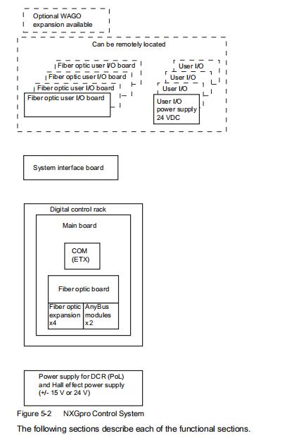
5.1.1 Digital Control Rack (DCR)
The NXGpro DCR consists of a three part combined system:
1. Main control board
2. Fiber optic board
3. Single board computer utilizing the ETX form factor attached to the main control board
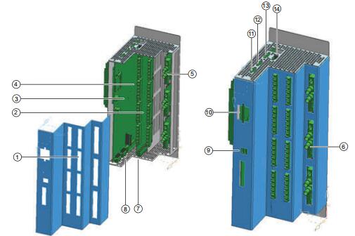
1 Cover with expansion knock-outs
2 Fiber optic expansion
3 Main control board
4 Fiber optic board
5 Network 1 (optional)
6 Network 2 (optional)
7 Bypass, FO user I/O, critical I/O and additional fiber optic communication
8 System interface
9 USB (2) ports
10 Compact flash drive
11 Modem/debug
12 Keypad
13 External user I/O (serial)
14 VGA
Figure 5-3 NXGpro Digital Control Rack (DCR)
Main Control Board
There are three main functions that are contained on the main control board:
● Digital: The digital sub-system section of the main control board, has a two part function:
– provide various data communication interfaces for the control.
– process the digitized motor feedback data from the analog section into pole firing
commands for the power cells.
● Analog: The analog sub-system section of the main control board has a three part function:
– receive analog motor feedback inputs.
– perform analog signal conditioning on the feedback input signals.
– convert the conditioned feedback signals into digital data.
● Power supply: The power supply section for the main control board is divided into three
parts:
– DC power input with redundancy
– DC to DC conversion with regulated outputs
– Power supply failure detection.
Fiber Optic Main Board/Fiber Optic Expansion Boards
Each fiber optic main board has a three part function:
● Connection point and signal driver for all of the fiber optic connections for the control system.
● Connection point for the Anybus network communication modules.
● Mechanical function utilizing different physical board dimensions which allow for the
appropriate fiber optic bend radius to be applied during the mechanical assembly of the
control cabinet.
The fiber optic expansion boards are a single rank (A,B,C phase) add on board to the fiber optic
main board and are used to expand the DCR from 12 power cell operation up to 24 power cell
operation. The power for the fiber optic expansion boards is sourced from the fiber optic main
board.
5.1.2 System Interface Board (SIB)
The system interface board (SIB) has a two part function:
1. interface between the drive system feedback and the DCR.
2. platform for a dedicated circuit for the drive input breaker control (M1 permissive).
NXGpro Control Description
5.1 Control System
30
NXGpro Control
Operating Manual, AJ, A5E33474566_EN
5.1.3 User I/O
The fiber optic user I/O board (user I/O is also referred to as internal I/O for backwards
compatibility with NXG systems) is designed to be the external customer interface connection
into the drive control system. Each user I/O has:
● 16 digital inputs
● 20 digital outputs
● 3 analog inputs
● 2 analog outputs
The user I/O are all contained within one board. Up to four user I/O can be connected together
to increase the number of I/O that are available for use. A single fiber optic user I/O board
requires a power supply capable of +24 VDC (+/-5%), 1 A at 50 C at a minimum.
The external WAGO I/O system may be included in certain applications but is not included in
all systems. Refer to Section Discrete External I/O via WAGO System for further information.
See also
Discrete External I/O via WAGO System (Page 66)
5.1.4 Control System Power Supply
The control uses an external AC/DC power supply. The external power supply design accepts
AC voltage input and produces a three part DC voltage output:
1. +12 VDC digital
2. +/-15 VDC analog
3. +/- Hall Effect (+/-15 VDC or +/-24 VDC option)
A single fiber optic user I/O board requires a power supply capable of +24 VDC (+/-5%), 1 A at
50 C at a minimum
5.1 Control System
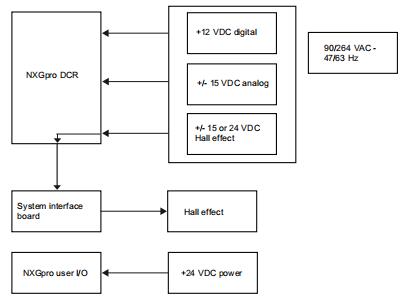
Figure 5-4 Functional Sections Interaction
5.2 Control Modes
Vector Control
SINAMICS PERFECT HARMONY GH180 drives use vector control to control induction motors
and synchronous motors. Vector control provides a framework that is simple to implement, and
performs nearly as well as a DC motor. Figure Vector Control Algorithms shows a simplified
representation of the vector control algorithms implemented in the drives. The basic
components of vector control are:
1. Motor model: determines motor flux, angle and speed.
2. Current regulators: these regulators are referred to as the inner loops.
3. Flux and speed regulators: these regulators are referred to as the outer loops.
4. Feed-forward (FF) compensation: improves the transient response of torque loop and flux
loop.
6.1 Non-user Accessible Interfaces
6.1.1 System Inputs and Outputs for Motor Control
The drive must have feedbacks from the system under control to function properly. Due to the
wide range of input voltages and currents, and due also to the dangerously high levels of both
input and output signals, interposing sensors are used to scale the signals to a safe and usable
level in the control cabinet, and present them to the controls. These are composed of input and
output voltage attenuators, input current transformers (CTs), and output Hall Effect sensors.
Detailed information, including values and locations of sensors, is described in the Operating
Instructions Manual for the specific system.
The signals are scaled in such a way as to present the same control level signals independent
of the source levels. This allows for a unitless control algorithm that is consistent in response
from application to application, since the rated values are entered once for the inputs, and the
drive responds in a similar fashion to scaled per unit signals. This is known as a normalized
system.
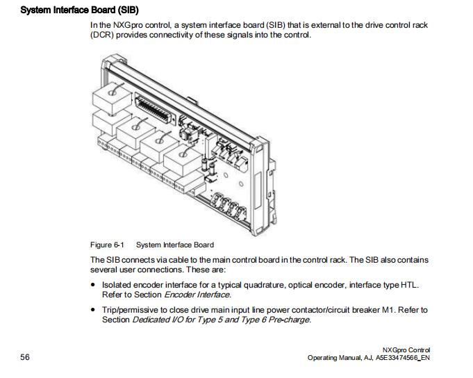
System Interface Board (SIB)
In the NXGpro control, a system interface board (SIB) that is external to the drive control rack
(DCR) provides connectivity of these signals into the control.
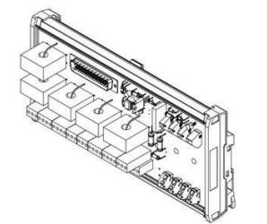
Figure 6-1 System Interface Board
The SIB connects via cable to the main control board in the control rack. The SIB also contains
several user connections. These are:
● Isolated encoder interface for a typical quadrature, optical encoder, interface type HTL.
Refer to Section Encoder Interface.
● Trip/permissive to close drive main input line power contactor/circuit breaker M1. Refer to
Section Dedicated I/O for Type 5 and Type 6 Pre-charge.
The following functions performed by the SIB provide a signal directly to the modulator to shut
down all cell switching immediately:
● Inhibit or CR3 signal to modulator. Refer to Section Inhibit Input (Control Relay 3, CR3)
6.1.5 Bypass Control
When the bypass option is installed, the cellular configuration of the power section ensures
that, if a critical component on a cell fails, the cell can be bypassed at the output of the cell and
the drive will continue to run at near full capability. This is done through output contactors for
each cell.
The modulator controls the activation of the bypass contactors via a fiber optic link to the
medium voltage (MV) bypass board. The MV bypass board contains driving and sensing
circuitry to interface to the cell-based output contactors. Via this interface, if the control trips on
a cell fault, it isolates the faulted cell, compensates for the neutral-shift to equalize the three
output phase voltages, and re-enables the drive output after a sub-second delay depending on
contactor travel time. This fast bypass feature provides maximum availability by making the cell
trip as transparent as possible to the system process.
DANGER
Electric Shock Hazard
Risk of death or serious injury.
The medium voltage bypass board is located in the high voltage section of the drive and is at
high voltage potential.
Components in this area must only be accessed by qualified Siemens personnel.
6.2.1 Human Machine Interface
The standard interface for the drive is the keypad which is detailed in Chapter Software User
Interface. This is used to control the drive, change parameters, and tune and monitor
performance. An optional touch screen HMI is offered running either the PC based tool or
application proprietary software.
In addition, a PC based tool can optionally be connected for remote control, configuration and
monitoring via an Ethernet connection. The drive tool includes all of the functionality of the
keypad plus it provides graphing capability for a number of internal control signals. The drive
tool is part of a collection of tools known collectively as the ToolSuite. Refer to the NXGpro
ToolSuite Software Manual for further information.
As part of the diagnostic capabilities of the NXGpro control, diagnostic information is available
through connection to the VGA port on the DCR. Control of the screens is achieved through the
use of a standard PC keyboard attached to one of the USB ports on the DCR. This capability
is also available through the ToolSuite software. Refer to the NXGpro ToolSuite Software
Manual for further information.
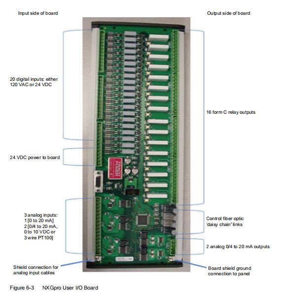
6.2.4.1 User I/O Board
Typically an NXGpro control system has a fiber optic connected user I/O board for system
interconnections. The first board is always used for the critical I/O of the system. Refer to
Section Dedicated I/O for the mapping of these I/O.
The control system can support up to three additional user I/O boards via fiber optic
communication. The boards may be remotely located up to 35 meters in fiber length. Available
boards support either all 24 V or all 120 V on their digital inputs. The digital inputs cannot be
mixed between the given voltage levels. The system is fixed for a particular voltage level by the
board chosen.
Hardware Interface Description
6.2 User Accessible Interfaces
Each board contains the following I/O:
I/O Type Number of I/O Ranges/Configuration
Analog input 3 ● #1 input: 0 to 20 mA or 4 to 20 mA.
● #2 and #3 inputs: Selectable between:
– 0 to 20 mA or
– 4 to 20 mA or
– 0 to 10 VDC or
– 3 wire 100 Ω RTD
Analog output 2 0 to 20 mA or 4 to 20 mA output
Digital input 20 All 24 VDC or all 120 VDC (depending on the board chosen)
Digital output 16 Form C Relay 1 Amp, 250 VAC, COSo = 0.4; 1 Amp, 30 VDC
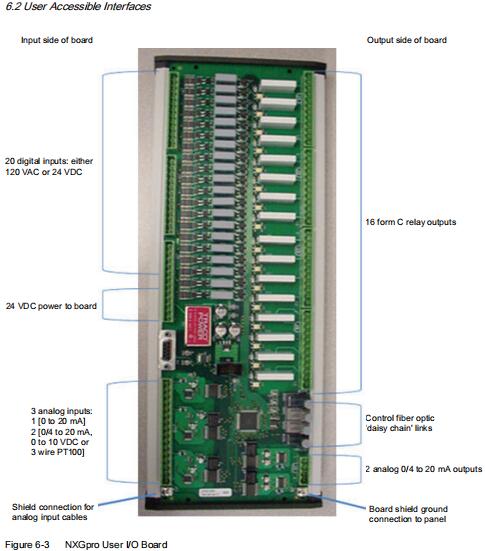
The 20 digital inputs are electrically isolated into five groups of four with a common low side
connection for each group. All terminals of the form C relays are available for the digital outputs.
The analog I/O are all individually isolated. The analog circuits are internally powered and do
not require a separate supply. In addition, the 0 to 10 V inputs provide an isolated 11 VDC
supply for the use of a 10 K Ohm potentiometer. While the circuits have a higher isolation rating,
the actual isolation is limited by the ratings of the connectors used (300 VAC). Actual usage of
these connections will depend on the individual wiring of the drive to the TB2 terminal strip.
Refer to the drive specific wiring diagrams.
While gain and offset adjustments of internal analog I/O is provided for in the software for
previous generations of equipment, the NXGpro user I/O boards do not require adjustment for
0 to 20 and 4 to 20 mA operation. Some minor adjustment may be required for 0 to 10 VDC and
RTD usage due to application variations.
The board has a built in controller which manages the I/O peripherals and also the
communication between the board and the system. Software options exist to allow for the
choice of last state, defined state or zero state in case of loss of communications with the
control. The board itself requires an external power supply of 24 VDC. Two power supply
connections are provided to allow for a redundant power supply option. The board does not
contain circuitry to detect loss of power supply at this time. The connections to the system are
simple and there are removable plug-in terminal blocks for I/O and power supply. The fiber
optics use the same modular snap and lock system as the cells and bypass. Two ground lugs
are provided for panel bonding and shielding.
The following table shows the I/O identifiers and SOP flag names for each I/O point on the user
I/O boards connected via fiber optic interconnection:
6.2.7 Network Connections
The control system has options for two network connections. These are supported through
Anybus modules installed within the DCR.
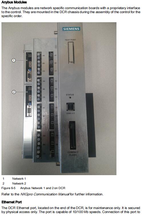
Anybus Modules
The Anybus modules are network specific communication boards with a proprietary interface
to the control. They are mounted in the DCR chassis during the assembly of the control for the
specific order.
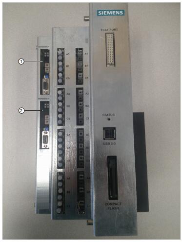
1 Network 1
2 Network 2
Figure 6-5 Anybus Network 1 and 2 on DCR
Refer to the NXGpro Communication Manual for further information.
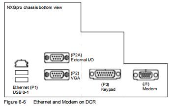
Ethernet Port
The DCR Ethernet port, located on the end of the DCR, is for maintenance only. It is secured
by physical access only. The port is capable of 10/100 Mb speeds. Connection of this port to
any etwork is strong discouraged. Refer to the NXGpro Communication Manual for further
information and supported protocols.
Modem
The modem port is a special case communication port for monitoring status of the drive only.
Refer to the NXGpro Communication Manual for further information.
10.1 SIMATIC Keypad
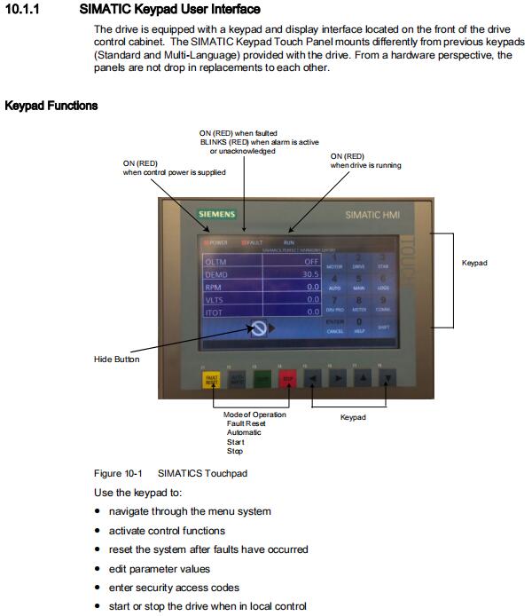
10.1.1 SIMATIC Keypad User Interface
The drive is equipped with a keypad and display interface located on the front of the drive
control cabinet. The SIMATIC Keypad Touch Panel mounts differently from previous keypads
(Standard and Multi-Language) provided with the drive. From a hardware perspective, the
panels are not drop in replacements to each other.
Keypad Functions
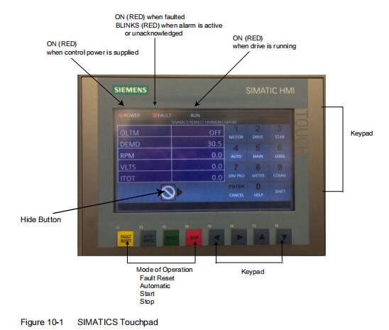
Use the keypad to:
● navigate through the menu system
● activate control functions
● reset the system after faults have occurred
● edit parameter values
● enter security access codes
● start or stop the drive when in local control
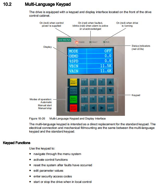
10.2 Multi-Language Keypad
The drive is equipped with a keypad and display interface located on the front of the drive
control cabinet.
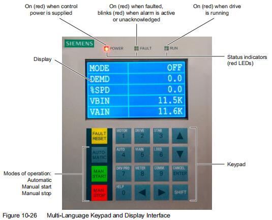
The multi-language keypad is intended as a direct replacement for the standard keypad. The
electrical connection and mechanical fit/mounting are the same between the multi-language
keypad and the standard keypad.
Keypad Functions
Use the keypad to:
● navigate through the menu system
● activate control functions
● reset the system after faults have occurred
● edit parameter values
● enter security access codes
● start or stop the drive when in local control
10.3 NXGpro ToolSuite
The NXGpro ToolSuite is a PC-based application software package that integrates various
software tools used for NXGpro based drives. One of the tools contained within ToolSuite is the
drive tool. The drive tool allows you to navigate through a drive’s features using a PC and a
mouse or touch screen, allowing you to monitor and control the drive’s functions. The drive tool
is a high-level GUI that runs on a PC equipped with a Microsoft Windows operating system. The
control, and the PC running the drive tool, interface with each other using ethernet and TCP/IP
protocols.
The structure of the menu hierarchy is slightly different with this tool than with the keypad. For
full coverage of the drive tool, refer to the NXGpro ToolSuite Software Manual.
| Spare Part | Item | Part Number | Description | MLFB | OLD PN |
| NXG pro DCR | NXGpro DCR 12 Cell | A5E33032452 | GH180 NXGpro controller 12 cell | 6SR0960-0CC12-0AD0 | |
| NXGpro DCR 15 Cell | A5E37764609 | GH180 NXGpro controller 15 cell | 6SR0960-0CC15-0AD0 | ||
| NXGpro DCR 18 Cell | A5E33032455 | GH180 NXGpro controller 18 cell | 6SR0960-0CC18-0AD0 | ||
| NXGpro DCR 21 Cell | A5E37764770 | GH180 NXGpro controller 21 cell | 6SR0960-0CC21-0AD0 | ||
| NXGpro DCR 24 Cell | A5E33032458 | GH180 NXGpro controller 24 cell | 6SR0960-0CC24-0AD0 | ||
| NXGpro CF | A5E35236834 | GH180 NXGpro compact flash card | 6SR0960-0CC08-0AD0 | ||
| SIB | A5E36968571 | GH180 NXGpro System Interface Board | 6SR0960-0CC16-0AD0 | A5E32168144 | |
| User I/O board 24VDV | A5E32100313 | GH180 24VDC User IO Board | 6SR0960-0CC07-1AD0 | ||
| USER I/O board POWER SUPPLY | A5E37356659 | GH180 NXGpro USER I/O board POWER SUPPLY | 6SR5902-0CM00-0AM0 | ||
| NXGpro CPS 15VDC | A5E37876282 | Power Supply NXGpro CPS +/-15V | 6SR0960-0CC32-0AD0 | ||
| NXGpro CPS 15VDC U55 | A5E34916937 | Power Supply NXGpro CPS +/-15V High Alt. | 6SR0960-0CC05-1AD0 | A5E34916905 | |
| NXGpro CPS 15&24VDC | A5E37877003 | Power Supply NXGpro CPS 15&24VDC | 6SR0960-0CC50-0AD0 | ||
| NXGpro CPS 15&24VDC U55 | A5E34916937 | Power Supply NXGpro CPS 15&24VDC High Alt. | |||
| NXGpro CPS 15&24VDC | A5E44722441 | Power Supply NXGpro CPS 15&24VDC | 6SR0960-0CC40-0AD0 | ||
| NXGpro-Profibus-DP | A1A099201 | COMM. KIT,ANYBUS Profibus-DP,NXGpro | 6SR0960-0DC00-0AD0 | ||
| NXGpro-DeviceNet | A1A098628 | COMM. KIT,ANYBUS DeviceNet,NXGpro | 6SR0960-0DC01-0AD0 | ||
| NXGpro-ModbusTCP/Eth | A1A099202 | OMM. KIT,ANYBUS ModbusTCP/Eth,NXGpro | 6SR0960-0DC02-0AD0 | ||
| NXGpro-ControlNet | A1A099203 | COMM KIT,ANYBUS ControlNet,NXGpro | 6SR0960-0DC03-0AD0 | ||
| NXGpro-MODBUS | A1A10000441.00 | COMM. KIT, MODBUS,NXGpro | 6SR0960-0DC04-0AD0 | ||
| Keypad kit | A5E02669561 | KEYPAD KIT (Chinese) | 6SR0960-0CC10-0AD0 | LDZ252090.11NGSC | |
| Keypad | A5E02624585 | MULTI LANGUAGE KEYPAD ASSEMBLY CHINESE | 6SR0960-0CB16-0AD0 | A1A460A68.23 | |
| keypad kit | A5E02669560 | KEYPAD KIT (English) | 6SR3900-0SM20-0BD0 | LDZ252090.11NGSC | |
| Keypad | A5E02363383 | MULTI LANGUAGE KEYPAD ASSEMBLY ENGLISH | 6SR0960-0CB15-0AD0 | A1A460A68.23 | |
| keypad kit | A5E02982002 | KEYPAD KIT (Russia) | 6SR0900-0CM07-0AD0 | LDZ252090.11NGSC | |
| Keypad | A5E02669580 | MULTI LANGUAGE KEYPAD ASSEMBLY RUSSIA | 6SR0960-0CB18-0AD0 | A1A460A68.23 | |
| keypad kit | A5E39808478 | KEYPAD KIT (Simatic) | 6SR0960-0SM60-0AD0 | ||
| KEYPAD | A5E39206479 | DEV_CONTROL_SIMATIC HMI, KTP700 BASIC D | 6SR4900-0SM00-0AM0 | ||
| NXGII DCR | NXGII DCR with FOHB kit | A5E33065979 | NXGII DCR with FOHB kit | 6SR0960-0CB01-0AM0 | |
| NXGII DCR without FOHB Kit | A5E03931016 | NXGII DCR without FOHB Kit | 6SR0960-0CB21-0AD0 | A1A10000313.00 | |
| NXGII DCR with FOHB kit U55 | A5E33561398 | NXGII DCR with FOHB kit U55 | 6SR0960-0CB02-0AM0 | ||
| NXGII DCR without FOHB Kit U55 | A5E33561420 | NXGII DCR without FOHB Kit U55 | 6SR0960-0CB04-0AM0 | ||
| Keypad adapter board | A1A10000283.01M | Keypad adapter board | 6SR0960-0SM23-0AD0 | ||
| System I/O Board | A1A10000423.00M | PCA, W/FIRMARE,NXG SYSTEM I/O | 6SR0960-0CB02-0AD0 | LDZ10000423.00C | |
| BGA Modulator | A1A10000350.00M | PCA, W/FIRMWARE, MODULATOR, | 6SR0960-0CB03-0AD0 | LDZ10000225.00C | |
| Communications Board | A5E03407403 | PCA, COMM BOARD | 6SR3960-0CD02-0AD0 | LDZ363818.00C /A1A363818.00M/461F11.00 | |
| Signal Control Board | A5E01708486 | PCA, SIGNAL CONDITIONING BOARD | 6SR0960-0CB14-0AD0 | LDZ01708486C/LDZ10000403.01C/363633.00 | |
| KEYPAD | A5E39206479 | DEV_CONTROL_SIMATIC HMI, KTP700 BASIC D | 6SR4900-0SM00-0AM0 | ||
| I/O Breakout Board 120 V I/O | A5E01649325 | PCA, I/O BREAKOUT BOARD,120VAC | 6SR0960-0CB07-1AD0 | LDZ01649325C | |
| I/O Breakout Board 24 V I/O | A5E01649374 | PCA COATED 24VDC INPUTS SYS I/O BRKOUT | 6SR0960-0CB07-2AD0 | LDZ01649374C | |
| NXGII Power Supply | A1A0100275 | POWER SUPPLY | 6SR0960-0CD01-1AD0 | ||
| NXGII Power Supply | A1A14000461.00 | POWER SUPPLY KIT | |||
| NXGII Power Supply U55 | A5E31055176 | POWER_SPLY | 6SR0960-0EM02-0AD0 | ||
| DCR FAN | A5E30653347 | AXIALFAN | 6SR0960-0GM02-0AD0 | A5E02381532/LDZ092828 | |
| NXG DCR | NXG DCR | A1A461R57.00 | NXG DCR | LDZ461R57.00C | |
| Keypad adapter board | A1A10000283.01M | Keypad adapter board | 6SR0960-0SM23-0AD0 | ||
| System I/O Board | A1A10000423.00M | PCA, W/FIRMARE,NXG SYSTEM I/O | 6SR0960-0CB02-0AD0 | ||
| BGA Modulator | A1A10000350.00M | PCA, W/FIRMWARE, MODULATOR, | 6SR0960-0CB03-0AD0 | ||
| Communications Board | A5E03407403 | PCA, COMM BOARD | 6SR3960-0CD02-0AD0 | LDZ363818.00C /A1A363818.00M | |
| NXG Power Supply | LDZ10501382 | Power Supply | 6SR3900-0KA00-0AM0 | ||
| Power supply module | LDZ10501501 | 750-612,WAGO POWER SUPPLY MODULE | 6SR0960-0RA36-0AD0 | ||
| WAGO power supply | A5E37356659 | NXGpro POWER SUPPLY | 6SR5902-0CM00-0AM0 | LDZ10501526 | |
| WAGO power supply | A5E30112609 | POWER_SPLY_230V_24V_10A | 6SR0960-0RA10-0AM0 | ||
| WAGO power supply | LDZ10501360 | POWER SUPPLY | 6SR5902-0SM01-0AM0 | ||
| UPS | UPS Pulsar 220VAC | LDZ10501472 | UPS 700VA,230V,50/60HZ | 6SR0960-0SM01-0AM0 | |
| UPS GES-N1K | A5E31321302 | UPS, 1000VA, 220V | 6SR0900-0KM02-0AM0 | ||
| UPS | A5E35632577 | POWER_SPLY_UPS | 6SR5902-0KM00-0AM0 | ||
| UPS 120VAC | A5E34166880 | UPS,700VA,120V,50/60HZ | 6SR0900-0KM03-0AM0 | A1A097618/LDZ097618C | |
| Cell Bypass | Bypass Contactor | LDZ14500013.00 | BYPASS CONTACTOR ASSY | 6SR3960-0EA01-0AM0 | |
| Bypass Control Board | A5E02634309 | PCA W/FIRMWARE, BYPASS CONTROL | 6SR0960-0EM08-0AD0 | LDZ363662.01C | |
| Power Supply For Bypass | A1A363549.00 | POWER SUPPLY ASSY FOR BYPASS | 6SR3960-0EA11-0AD0 | LDZ363549.00C | |
| Cell Bypass | Bypass Contactor | A5E02610994 | HIGH CURR.CONTACTOR ASSY | 6SR3960-0EA00-0AM0 | A1A10000070.00 |
| Bypass Control Board | A1A10000416.00M | PCA W/FIRMWARE, BYPASS CONTROL | 6SR0960-0EA03-0AD0 | LDZ363662.00C | |
| Cell Bypass | BYPASS CONTATOR | A5E02634363 | BYPASS CONTACTOR | 6SR3960-0EA01-1AM0 | |
| PCA BYPASS CONTROL | A5E02634309 | PCA W/FIRMWARE, BYPASS CONTROL | 6SR0960-0EM08-0AD0 | LDZ363662.01C | |
| BYPASS POWER SUPPLY | A5E38384485 | POWER SUPPLY ASSY,BYPASS,uH | 6SR4900-0EM05-0AM1 | LDZ10000484.00C | |
| CELL BYPASS | BYPASS CONTACTOR | A5E03772188 | BYPASS CONTACTOR ASSY | 6SR4900-0EM01-0AM0 | |
| BYPASS CONTATOR ASSEMBLY | A5E34919093 | BYPASS CONTACTOR | 6SR4900-0EM06-0AM0 | ||
| BYPASS CONTATOR | A5E02634363 | BYPASS CONTACTOR | 6SR3960-0EA01-1AM0 | ||
| POWER SUPPLY | A5E38384485 | POWER SUPPLY ASSY, BYPASS, Uh | 6SR4900-0EM05-0AM1 | LDZ10000484.00C | |
| BYPASS BOARD | A5E02634309 | PCA,W/FIRMWARE,BYPASS | 6SR0960-0EM08-0AD0 | LDZ363662.01C | |
| Cell Bypass | BYPASS CONTATOR | A5E32187356 | BYPASS CONTACTOR | 6SR4900-0EM00-0AM0 | |
| BYPASS CONTATOR | A5E02634363 | BYPASS CONTACTOR | 6SR3960-0EA01-1AM0 | ||
| BYPASS CONTATOR | A5E35230339 | BYPASS CONTACTOR | 6SR4900-0EM04-0AM0 | ||
| PCA BYPASS CONTROL | A5E02634309 | PCA W/FIRMWARE, BYPASS CONTROL | 6SR0960-0EM08-0AD0 | LDZ363662.01C | |
| BYPASS POWER SUPPLY | A5E38384485 | POWER SUPPLY ASSY,BYPASS,uH | 6SR4900-0EM05-0AM1 | ||
| WAGO RELAY | LDZ10501494 | WAGO RELAY MODULE | 6SR0900-0RM04-0AM0 | ||
| CELL BYPASS | BYPASS CONTATOR | A5E02634363 | BYPASS CONTACTOR | 6SR3960-0EA01-1AM0 | |
| BYPASS CONTATOR | A5E35230339 | BYPASS CONTACTOR | 6SR4900-0EM04-0AM0 | ||
| PCA BYPASS CONTROL | A5E02634309 | PCA W/FIRMWARE, BYPASS CONTROL | 6SR0960-0EM08-0AD0 | ||
| BYPASS POWER SUPPLY | A5E38384485 | POWER SUPPLY ASSY,BYPASS,Uh | 6SR4900-0EM05-0AM1 | ||
| BYPASS CONTATOR | A5E42921775 | BYPASS CONTACTOR | 6SR4900-0EM07-0AM0 | ||
| BYPASS CONTATOR | A5E35963048 | BYPASS CONTACTOR | 6SR3900-0KM04-0AM0 | ||
| PCA BYPASS CONTROL | A1A10000416.00M | PCA W/FIRMWARE, BYPASS CONTROL | 6SR0960-0EA03-0AD0 | ||
| BYPASS POWER SUPPLY | A5E33720060 | POWER SUPPLY ASSY,BYPASS,Uh | 6SR0960-0EM18-0AD0 | ||
| Cell Bypass | PCA BYPASS CONTROL | A5E37926678 | PCA W/FIRMWARE, BYPASS CONTROL | 6SR5900-0EM01-0AD0 | |
| PCA BYPASS CONTROL | A5E40857482 | PCA W/FIRMWARE, BYPASS CONTROL | 6SR0960-0AM83-0AD0 | ||
| BYPASS POWER SUPPLY | A5E38292328 | POWER SUPPLY ASSY,BYPASS,uH | 6SR5902-0EM00-0AM0 | ||
| CELL BYPASS | BYPASS | A5E37110177 | BYPASS CONTACTOR ASSEMBLE | ||
| BYPASS | A5E40727031 | BYPASS CONTACTOR ASSEMBLE | |||
| Cell Bypass | BYPASS CONTATOR | A5E02610994 | BYPASS CONTACTOR | 6SR3960-0EA00-0AM0 | |
| PCA BYPASS CONTROL | A1A10000416.00M | PCA W/FIRMWARE, BYPASS CONTROL | 6SR0960-0EA03-0AD0 | ||
| BYPASS POWER SUPPLY | A1A363634.01 | POWER SUPPLY ASSY,BYPASS,uH | 6SR3960-0EA01-0AD0 |
Previous : A1A10000623.00M CPU Kit, A1A0100521 CPU Board, A1A10000283.01M Keypad adapter board, A1A260986.00 CF
Next : Siemens Robicon CCB A1A10000432.55M, A1A10000432.54M, A1A10000432.53M, A1A10000432.52M


 Copy product links
 Long by picture save/share
Siemens Medium-Voltage Drive SINAMICS PERFECT HARMONY GH180 NXGpro Control Operating Manual for v6.8
INQUIRY


Add Successfully
We are the world's leading supplier of spare parts for medium voltage drives of various brands

点击右上角
分享给朋友吧
GET IN TOUCH

East Sun Industrial Centre, No 16 Shing Yip Street Kl, Hongkong

Call us : +852 5261 7322

Email us : [email protected]
SITEMAP
BUSINESS HOURS
Monday to Friday : 9 am to 6 pm
Saturday : 9 am to 12 am
Sunday : Closed Support Hours in 24/7 Everyday
DISCLAIMER:
We are not an authorized distributor, reseller or representative of the following products presented on this website. All Product names and logos throughout this site are trademarks of their respective holders. Use of them DOES NOT imply any affiliation with or endorsement by them.
© 2020 robiconperfectharmony.com site . All rights reserved Site Map
