

Siemens Robicon Perfect Harmony GH180 NXG NXGpro NXG controller Tool Suite 6.4.1 GenIV GenI GenII
Siemens Robicon Perfect Harmony GH180 NXG NXGpro NXG controller Tool Suite 6.4.1 GenIV GenI GenII
What generates the SCR Bypass Fault in Robicon 454gt VFD?
Could be due to SCR failure in DC Bus stage. The SCR not turning ON /could be due to precharge resistance fail or SCR itself fail. You can check the ohmic value of SCR in OFF condition
Regards,
Vijay
Siemens SINAMICS Perfect Harmony GH180 GH150 problem with Down Transfer
Good day
There is a problem: It does not work Synchronous Down Transfer
Drive Robicon Perfect Harmony with the function of synchronous transfer to work on five of the synchronous motor pumps of 2,2MW each. Commissioning is present. Full Load unavailable yet. The drive successfully works in test modes also successfully works with the motor in SMC mode. Also successfully tested Synchronous Up Transfer. The UpTransfer takes place smoothly without jumps, according to instructions.
The problem arises during the DownTransfer procedure
1.PLC sends a request «DownTransferRequest»
2 Drive gives the answer «DownTransferPermit»
3. PLC close the VFD contactor
4 The drive receives a signal «VFDContactorAcknowlege», while LineContactor closed and the drive has received a «LineContactorAcknowlege»
5 Down Transfer is starting.
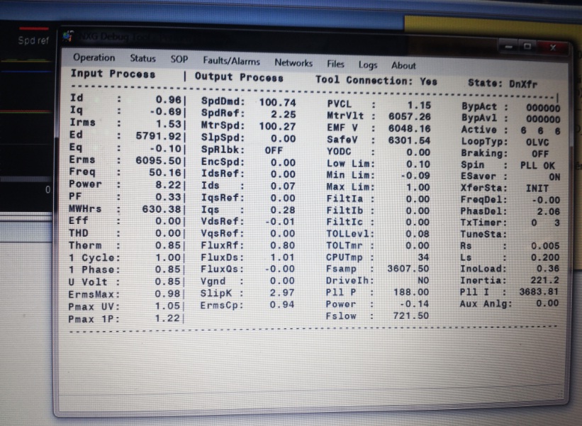
6 Monitor the status of being in the Debug TooL (tab Synch Transfer Status)
The first state after the DownTranfer start - Waiting for Frequency Lock, then Waiting for Torque to build. During this little modification of Input Current and Output Current are present. After some time on the drive occure error «_Cell number_ DC bus over volt». Cell number is random always.
The field Reference in the process of DownTransfer has not been lodged.
The logic of the PLC switches the Exiter to the work from the drive with a signal «LineContactorUnlatch», but the drive does not produce this signal. Also, the instructions are not described in which moments should be submitted / shoot excitement during the down transfer on the synchronous motor.
According to the instructions, we execute a total inspection of each cell, and their connection to the busbars, and didn’t find any defect. Also in the instructions indicated that the values of the parameters Spinning Load sufficient for most applications. And in general, there isnt instruction for setting up the DownTransfer
Maybe someone will say what we are doing wrong and what we need to do to make the Down Transfer.
I can provide Event Log Parametr Dump and Screen Captured video during the Down Transfer
With Best Regards
Hi boyn84,
Have you made the following parameter changes?
Enable Spinning Load by setting Spinning Load Mode (2430) to Forward.
Set the Speed Fwd Max Limit1 (2080) to at least 105%.
Do you have a copy of NXG Control Manual A1AD19001588?
Good day
I have changed marked parameters and DownTransfer gone to next step, but finally we couldnt finish DownTranfer cours we fased with new problem with exiter. When line contactor unlatch and Exiter got the LineContactorAcknowlege signal, Exiter logic shut down the exitation and does not react to signal "Work via VFD". Exiter logic changing is not a technical problem for us but it is a organisation and finansial problem for our Client.
So anyway thank You very much for your help
With Best Regards
Dear Sir,This is regarding the query about Siemens Robicon Perfect harmony problem,
The perfect harmony drive is of Gen 3, 1600KW,2500KVA,260A
The problem is this drive is not running continuously on bypass mode, There are 6 cells/phase. In Rack B there is one cell faulty, on become one cell inactive the bypass contactor has picked & Drive run successfully, but after running 15 days, intermediately/unpredictably/atanyload the Bypass acknowledge failed fault comes who energies the Bypass fault & Drive shutdown on this fault,For avoid this fault I have replaced the Bypass relay board, Power supply to bypass relay board, OFC cable of Modulator board to Bypass relay board, Modulator board & By pass contactor also with new one.But the result is same, Fault comes intermedietely & uptill now this faults happens more than 5 times.
Now What could be the reason from which the drive trips intermediately?One more query parallel to this, How the sensing is going (Complete Process) to modulator board that whether the Bypass contactor has hold or de-hold?You are request to please go through it & Suggest your valuable answer.
For your reference parameter upload is attached.
If there is any other input required please let me know
Regards
Neeraj
Fault Name
Bypass Acknowledge Failed
Displayed Message
Bypass Ack failed
Description of fault/alarm
A fault/alarm is asserted if the bypass contactor that was commanded to be closed is not acknowledged by the MV Bypass board.
Associated Parameters
There are no specific parameters that affect this fault, but the fault will only occur on systems equipped with Mechanical Cell Bypass and it must be enabled in “Bypass type” (Menu ID 2520) by setting it equal to “Mech”.
Hysterisis or Delay
Faults have no delay or hysterisis. Alarms use hysterisis before being triggered. Before version 2.3 the alarm hysterisis was 30 fault system samples or 1/10 second before an alarm was issued. After version 2.3 the alarm hysterisis is now 150 fault system samples or ½ second before an alarm is issued.
Data Source
Specific Cell bypass contactor that was commanded to activate.
Variables in Data Source
None
SOP Flags That Affect Operation
None
System Location of Data Source
All bypass contactors are located next to each Cell in the Cell Cabinet of the Drive.
Potential Issues that affect the fault performance
Variations or inoperability of the Cell bypass system: Cell Bypass contactor, MV Bypass Power supply, MV Bypass board, Modulator board, and Fiber Optic link between the Modulator and the MV Bypass board.
Corrective action for deficiencies
Verify the Fiber Optic connection between the Modulator board and MV Bypass board is intact
Check/Replace MV Bypass board power supply
Replace MV Bypass board
Replace Modulator board
One time I had the same issue but problem fixed afte replacing FOC between modulator board and bypass board. If it is air cooled, some times dust accumlation on FOC end connectors also causes this.
Not sure how bypass Contactor ON is acknowledged. But do you have access for backside of panel.
you can check if any soldering went off loose at contactor side. or as the other thread suggested you can swap the cell for elimination
Regards,
Vijay
We are having 3 installations of Siemens Robicon SINAMICS perfect harmony drive GH180 GH150
After stoppage of about 1 month when we atarted one of the drive
"Hall effect" fault is coming and drive is getting tripped after about 1-2 hrs of run
Can u pls give your advice regarding the same
Dear all,
We have 2500 KV Robicon Perfect Hormony drive for Bag house fan.In running drive is tripped with "Input Protection fault" and after master reset drive is coming healthy.
product name :AC Variable Frequency drive,WCIII, Liquid cooled perfect harmony drive
Input :6.6K V and Output :2.5KV
Cell size :800-1200 Amps.
Plz any one give me solution to sort out the problem.
Satish
Input Protection faults are a group of faults associated with possible transformer failure or other reasons to trip the incoming HV supply (such as door switches or earthing switch interlocks).
You should not clear down an input protection fault without fully understanding why it occured, which would include reading the event log and would probably be best handled by a service call from a Siemens engineer.
Some Gen IV drives set input protection faults if the doors are opened, and the method of detecting those and resetting the fault relay should be in the manual.
long humming loud noise from the drive transformer
Hello,
I have a project for two Robicon Perfect Harmony drives, where only one is running and second one is in standby.
Because there will be long term between changing drives, there is neccessary to check motor and cable insulation status before drive start.
Is there some possibility (or option) to check motor cable and motor insulation status before drive start?
I mean some built-inmonitor of insulation status like f.e.cabinet Sinamicsdrives has (Bender insulation monitor).
Thanks
Martin
The best way for the Robicon drive is to also use a Bender unit with a voltage coupler. The drive can generate a output ground fault alarm itself but the Bender unit does the job better and gives you an analogue reading for the insulation resistance. Also I wouldn’t trust the internal drive ground fault alarm anywhere near as much as the Bender relay. If the insulation check is critical for your application install a Bender relay.
Thank you will4, I checked, whether this monitoring is in manuals for robicon.
But I found only ways how robicon check ground fault.
Also there was mentioned Bender monitor used in Sinamics drives.
I think it is good solution.
Thank you
I worked with a SINAMICS PERFECT HARMONY GH180 GENIII Aircooled VFD with cell bypass option. One day the drive trippedall of a sudden on "Cell Communication Fault" Cell bypass card power supplies checked and found no abnormality. The Cell Modulator board and FOC between DCR and Cell bypass circuit replaced and the problem never repeated.
My question is why the drive should trip in case of the above situation. If at all any cell fails, cell bypass should not have been worked. But without any cell failure how come it will trip a otherwise healthy drive.
Regards,
V.K.
Hi Bob
My question is phsyically when there is no cell fault and for mere communication issue why the drive should trip. Mechanical bypass enabled and it will come into picture if real cell fails. My case no cell failure still due to communication link problem with Cell Control board to bypass board drive tripped defeating the cell bypass option
Regards,
Vijay
Dear All,
can anybody provide Manuals/Document regarding Robicon MV Drive Gen-3 series?
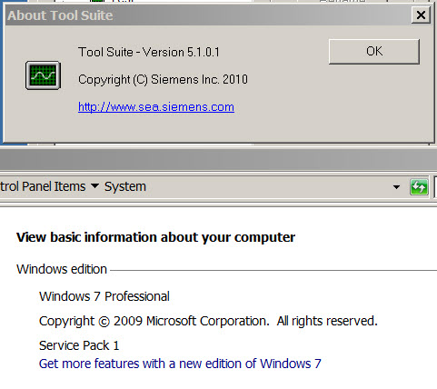
I also need setup for "Tool suit" which is used to go online using pc with robicon.
Regards
Ashish
GEN3_e user manual A1A19000405A V1.3 attached.
Tool Suite required for ROBICON PERFECT HARMONY (GEN IV)
Gentleman
I would like to get help for getting Tool suite for viewing then parameters (Events, logs, alarms). for the following VFD drives.
Type : ROBICON PERFECT HARMONY (GEN IV)
Model No. : 6SR 4102-0dd41-0AK0-Z
Cell rating : 140 Amps
Cell Voltage : 750 Volts
Incoming voltage : 4160 Volts
With best regards
Favas
Hi.
From Siemens:
We have commissioning checklists that are very detailed. Please contact Siemens at 800-333-7421
We have a 24/7 customer support number (800-333-7421) that can address your technical questions about the drive documentation.
Best regards.
Hi everyone,
I'm looking for manuals or anything about a Robicon PH communication viamodbus to a dcs CPU. I'm sorry if it's too basic, but I just can't find anything about it.If u haveany thing regarding modbus communicationI would appreciate if u share post the url.
Best regards
jarrar
one drive with 2 motors
We have one Robicon Perfect harmony drive Gen IV - 6SR41022HE420BG0-Z (6.6kV, 1500kW).
At present we are running one motor (6.6kV, 1500kW) with this drive (once in a week).
We have one another motor of 6.6kV, 315kW and want to run this 315kW motor from this drive during ideal time.
Is there any option where we can define two parameter set and used one set at a time which is required rather than entering all parameters again?
Hi Deep
As the voltage of both the motors is same 6.6KV, there are hardly 4 parameters to enter
Full load speed, Motor Frequency, Full load current, Motor KW rating. Most of the other limits are defined as % of name plate values so no need to disturb them like over load, no load current etc.
OR IF speed and frequency of both the motors is also same remaining are only 2 parameters
Or else you can create two cfg. files with separate motor data and save themat separte location on a PC with tool suit SW to connect to drive . You can load the respective cfg file as per your requirement.
PS : is there any specific reason to run the lower KW motor during idle time?
Regards,
Vijay
Hi Deep,
You can set up multiple configuration files (slaves) for multiple motors. You could then use a digital input to switch between the two files/motors in the SOP. The digital input could be driven by a key switch or similar. The NXG control manual A1A19001588 outlines the setting up of the two configuration files.
Hi
I am looking to have spare parts for ROBICON drives. All the manuals mention Robicon part number
only like A1A1.... but where I can get equivalent SIEMENS MLFB 6SR....
Regards,
Vijay
Reference for exiter from Robicon
Good day Ladies and Gentlemens
Maybe somebody will help me. I need to realize the reference for exiter with the Synch. Motor Field Current Command. Can i convert the 4-20mA signal of Field Reference to The Digital Potentiometer signal by Robicon PH means?
Hi
Robicon is used normally to vary the speed of a synchronous or asynchronous MV AC motor
If I am correct, you are looking for DC excitation current mounted externally on a synchronous motor. In this case you should go for 6RA70 DC Master for excitation current control.
Regards,
Vijay
Experts,
Today I encountered a problem with Robicon W120cpdrive (PM240)when conducting load test.
First, when testing drive with motor uncoupled, the drive can ramp up to 60hz without any fault. However, when testing under load, the drive tripped around 46 hz with fault F00020 saying that: main phase missing.
I did check the input side wire connection, and they seem good.
I also restore to factory setting and re-do all the commissioning again, the problem is still there. Please give me some help and I still on the jobsite.
Thanks in advance
Hello,
it looks like fault on input side wire connection, because the inverter can run with 2 phase till 60% load.
Measure the current to be sure.
Hello,
In ingeneering manual I found figure which shows a connection overview of the Siemens Robicon GenIV converters. But, It is note that this is an overview connection diagram. For detailed plant configuration, see schematic (circuit) diagrams. Where can I get it?
Hi,
Schematic drawings are nothing but your plant specific control connections from DCS or Field PB station to Robicon VFD like TB2 terminations or TB2ELV connections , motor RTD connections, Emergency stop connections, motor cooling blower connections etc. depending on interface to DCS and field . Usually these shall come along with drive during dipatch either in form of hard copy or as CD or both. If found missing you can contact your local siemens representative indicating drive part number, serial number and SO number which will be very much stickered inside the panel on door.
Regards,
Vijay
IGBT problem in UPS
Hello,
We have two UPS (three phase,400V, 30Kva) in parallel and redundant operation. IGBT (inverter power module) failure arises in one UPS few months back,after replacement of power module complet set it was making in operation. But un-fortunately the second UPS has same problem after two months of parallel operation. We could not come to any conclusion / point which is creating the problem. Because there is no fault observed in the output circuit. However, the output neutral is in floating mode and presently with one UPS is drawing more amperes than phases. New power module for second UPS is under procurement.
Can any one help us to resolve this issue, before installation of inverter unit.
Regards,
Muhammad Tariq Aziz
Hello,
What type of these UPS are, online or offline? What load they are supplying? Please provide more details.
You have mentioned as, two numbers UPS are connected parallel. When any one failed, do you run the system with 1 UPS or using another UPS? Please clarify. Have you measuer the loading of individual UPS on load? Please provide the specifications of UPS & power batteries connected.
Please provide details of above point.
Robicon Perfect Harmony PH drive Gen IV
Dear All,
ROBICON threads where to be posted?
Recently I faced a problem with GEN IV PH Robicon drive. As soon as I switch on Aux 480 V , "Input Protection Fault" is appearing on screen. After Latch Fault Relay reset through switch it is getting reset. Every start up is with same problem. What could be the root cause. Is it form breakout IO board. I checked the LFR and found coil is alright.
Drive Input : 13.8 KV
Output: 0-4160 V AC, 200 A rating.
Thanks in advance.
Vijay
Dear All,
I forgotten to mention the drive MLFB,
MLFB : 6SR4102-0DD41-0AK0-Z
Sl. No.: W4143622-00002
Help me out,
Regards,
Vijay
Dear All,
This excessive drive losses trip (idle) has bee resolved by upgrading NXG firmware to latest version 5.2.2
Cheers
Vijay
I found some of the ROBICON GENIV drives tripping on sporadic faults excessive dirve losses (idle). Identified the need to upgrade NXG to 5.2.2. Any link or folder for this software.
Thanking you
Vijay
Hello Experts,
Please, can any one broadly explains the difference between Thyristers & IGBTs?Some manufactures are supplying inverts of capacity 200 KW powerat 3 KHz frequency with thyristers while others are supplying with IGBTs? Why is it so?
Thanks in advance.
DEEP.
Hello Deepstra;
Thyristors and IGBTs are based on different technologies, but can be used for similar applications. The basic difference is that the thyristor is based on a 4-layer bipolar transistor, while the IGBT is based on a 4-layer MOSFET design, See here, on Wikipedia:
http://en.wikipedia.org/wiki/Thyristors
http://en.wikipedia.org/wiki/IGBT
IGBTs and thyristors both have a control "gate" that controls the firing angle of the output current, and can withstand high-power levelsused to control theoutput signal of a VFD. See the explanations on this article:
http://en.wikipedia.org/wiki/Variable-frequency_drive
All VFDs use their output devices (IGBTs, transistors, thyristors) only as switches, turning them only on or off. Using a linear device such as a transistor in its linear mode is impractical for a VFD drive, since the power dissipated in the drive devices would be about as much as the power delivered to the load,
The inverter circuit is probably the most important section of the VFD, changing DC energy into three channels of AC energy that can be used by an AC motor.
The usual method used to achieve variable motor voltage is pulse-width modulation (PWM). With PWM voltage control, the inverter switches are used to construct a quasi-sinusoidal output waveform by a series of narrow voltage pulses with pseudosinusoidal varying pulse durations,(Note: this is the part of the VFD where thyristorsor IGBTs circuitsare required).
As new types of semiconductor switches have been introduced, these have promptly been applied to inverter circuits at all voltage and current ratings for which suitable devices are available. Introduced in the 1980s, the insulated-gate bipolar transistor (IGBT) became the device used in most VFD inverter circuits in the first decade of the 21st century.
Hope this helps,
Daniel Chartier
Hello dchartier,
Great job,really thanks for your detail reply. It helped me a lot to understand the basic concepts. Moreover what I would like to know is, in inverter power supply application say 200 Kw, why some manufacturers are supplying with IGBTs & some with Thyristerised? What is the difference?
When the application is same, then why is the difference? I think there must be some point, say like current or power handling capacity, duty cycle or faster functioning, or response etc. Is it so.
One more question, can the thyristers be triggered at same high frequency as that ofIGBTs?
Hope my question is clear now.
Regards,
DEEP.
Hello Deep;
Thank you for your compliments, however undeserved they are. I only looked for information to complement my working experiences, so you could find your own answers.
I don't feel very confident about answering your new questions either. My experience has often been that with HV drives you tend to find more manufacturers using thyristors in their powerswitching sections. My most marking memory was working with (inside of?) a Robicon drive, rated for 10 MW (yes, that was kind of impressive! it occupied a 50 meters square floor print) where all the rectification and switching stages were built on "hockey-pucks", 10 cm diameter SCRs (thyristors). When I asked the technician from Robicon why they chose this technology, he said that it was because at these power levels the thyristors were more resiliant, and when they blew (and it did happen a lot during commissioning) they were cheaper and easierto replace than IGBTs.
In any case, have a look at this document discussing and comparing different technologies of switching transistos for MV and HV drives. It might just give you somedetails on the differences between technologies.
https://www.robiconperfectharmony.com/pdf/MV_AC_Drive_Topology_Analysis.pdf
Hope this helps,
Daniel Chartier
Robicon Perfect Harmony ID-PWM 454 GT Series HELP!
I have a problem with the AREF INPUTS on the old 454 GT Drive. I have beenover the settings a thousand times in the menu's, but the Analog inputs are being held at 11ma. No change with simulator, Pressure TX,EVEN when no input is hooked up at all!
As a result the VFD runs at one speed in Auto. I can speed up and slow down the VFD in manual however. I am useing a 4-20ma singnal from a PT to control the VFD Speed. REAL SIMPLE (or it should be)Are the VFD inputs toast? Or am I missing something?
Simotion with Robicon Perfect Harmony drives and possibly WinCC
Hi Ashish
Did you find a solution to Simotion/WinCC connection?
I am interested as we have to provide a similiar system using Simotion with Robicon Perfect Harmony drives and possibly WinCC. Would it be better to use WinCC-Flex?
thanks
Rob
Hello
I am a controls engineer and I am in charge of commissioning a pump station soon. The pump station has 4 Robicon Harmony GenIIIe drives. Model Number 6SR3102-5-G44-0.0.
I need drive documentation. Any drive documentation that shipped with the drive cannot be located. I am requesting User Manual, and Programming Manual and troublshooting guide. also is there any software available to program the drive using a lap top.
Any help in this would be appreciated.
Thanks
Goerge211
Hi
so I guess the model number of the robicon drive isn't good enough for siemens to locate a english version of the user manual.
So here is a siemens part number 31500556
S.O. Number 3000493183
Siemens Electrical Drives (Shanghai) Ltd.
George211
This is a slightly odd situation. Where are you Santiago?
I ask because the project engineer who specifies and supplies the drive normally ships all necessary manuals to the customer before delivery. Your best bet is to identify and call directly to the project engineer. That's also the best route for getting circuit diagrams, although there should be paper copies in the drive.
Commissioning is normally done by robicon-trained Siemens staff.
Thanks, Bob. I asked that, because we just starting project andnow gathering info about all whatare going to use inthat project. So, how I understood, all neccesary information would be supplied with drives?
In my experience, yes.
But it is not normal to commission your fist one with the book in one hand! Very good training is available from Nuernberg and Pittsburgh
Comms from Starter to G-120 (W-120)
Since the previous thread I found on this did not show a useful answer, I am trying again.
In my case the VFD is a 'W-120 Robicon' which is a G-120 (CM240S DP) with an AOP30 HMI (and some script adjustments). I can not get Starter to connect with it with my own serial cable or the one attached to the AOP30. PG/PC interface set correctly, diagnostic test comes up with a node (0) checked, but it won't connect further. I am using a newer PC (Windows XP) that has no serial port, so I am using a USB to Serial connector (found in this forum), an SW-4282. I tried another USB to Serial and had the same results. I know it is possible to connect as listed in the first post here (did it in training class in GA using the desktop computer).
What am I doing wrong?
Previous : Siemens Robicon Perfect Harmony GH180 NXG NXGpro NXG controller Tool Suite Latest Version 6.4.1
Next : Siemens Robicon GH180 GM150 SM150 SL150 WCIII GenIV Genllle A1A260986.00 Compact Flash card CF card


 Copy product links
 Long by picture save/share
INQUIRY


Add Successfully
We are the world's leading supplier of spare parts for medium voltage drives of various brands

点击右上角
分享给朋友吧
GET IN TOUCH

East Sun Industrial Centre, No 16 Shing Yip Street Kl, Hongkong

Call us : +852 5261 7322

Email us : [email protected]
SITEMAP
BUSINESS HOURS
Monday to Friday : 9 am to 6 pm
Saturday : 9 am to 12 am
Sunday : Closed Support Hours in 24/7 Everyday
DISCLAIMER:
We are not an authorized distributor, reseller or representative of the following products presented on this website. All Product names and logos throughout this site are trademarks of their respective holders. Use of them DOES NOT imply any affiliation with or endorsement by them.
© 2020 robiconperfectharmony.com site . All rights reserved Site Map
