

XP Power Power supply 700 W Siemens Robicon 6SR0960-0CD01-1AD0 F7E1A6G2 F7A4K6G2 F7A4K6G7 F7A4G2G2
XP Power Power supply 700 W Siemens Robicon 6SR0960-0CD01-1AD0 F7E1A6G2 F7A4K6G2 F7A4K6G7 F7A4G2G2
XP Power Power supply 700 W Siemens Robicon 6SR0960-0CD01-1AD0 F7E1A6G2 F7A4K6G2 F7A4K6G7 F7A4G2G2
Product
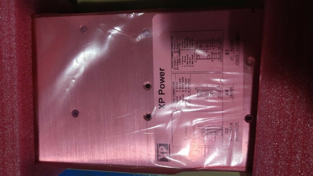
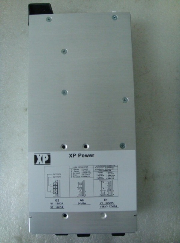
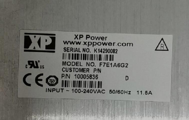
Article Number (Market Facing Number) F7E1A6G2
Product Description Power supply 700 W
Product family Not available
Product Lifecycle (PLM) PM300:Active Product
Price data
Price Group / Headquarter Price Group 6ZZ
List Price Price On Request
Customer Price Price On Request
Surcharge for Raw Materials None
Metal Factor None
Delivery information
Export Control Regulations ECCN : EAR99I / AL : N
Standard lead time ex-works 110 Day/Days
Net Weight (kg) 2.2 Kg
Product Dimensions (W x L x H) Not available
Packaging Dimension Not available
Package size unit of measure Not available
Quantity Unit 1 Piece
Packaging Quantity 1
Additional Product Information
EAN Not available
UPC Not available
Commodity Code 8504407018
LKZ_FDB/ CatalogID D15.2LDSP
Product Group 3662
Country of origin China
Compliance with the substance restrictions according to RoHS directive not available
Product class A: Standard product which is a stock item could be returned within the returns guidelines/period.
Obligation Category for taking back electrical and electronic equipment after use No obligation to take back electrical and electronic equipment after use
Classifications
Not available
A
C
-
D
C
Specification
300-2400 Watts
• Configurable for Fast Time to Market
• 1 to 24 Outputs
• Floating Outputs
• Fully Featured Signal Set
• SEMI F47 Compliant
• Extra Power Available at High Line
• 3 Year Warranty
MP Series
Input
Input Voltage • 90-264 VAC
Input Frequency • 47-63 Hz
Inrush Current • 40 A max at 230 VAC, cold start 25 °C
Power Factor • Compliant with EN61000-3-2, Class A
Earth Leakage Current • <1.5 mA
Input Protection • F3/FF: Internal T6.3 A/250 V fuse in line
F4/F6: Internal T10 A/250 V fuse in line
F7: Internal T12 A/250 V fuse in line
F8: Internal T15 A/250 V fuse in line
FX: Internal T20 A/250 V fuse in line
Output
Output Voltage • See module table
Output Voltage Trim • ±5% typical all outputs
Hold Up Time • 20 ms min
Line Regulation • Typically 0.1%, maximum 0.3%
Load Regulation • 1% max for single output modules
& V1 of dual & triple output modules.
2% max for V2 & V3 of dual & triple
output modules. The E module requires
up to 10% load & the K module up to 5%
load on V1 to achieve the specified
regulation figures on V2 & V3
Ripple & Noise • 50 mV or 1% pk-pk, whichever is greater,
20 MHz bandwidth
Overvoltage Protection • 115-130% Vnom for single output and output 1 of dual & triple output modules. No
OVP fitted to G modules or H modules.
Overload Protection • <150% of nominal rating
Short Circuit Protection • Continuous trip & restart (Hiccup mode)
Temperature • 0.03%/°C
Coefficient
Remote Sense • See signals & controls page
Current Share • Single wire parallel current share.
See signals & controls page
Inhibit • TTL compatible.
See signals & controls page
xppower.com
General
Efficiency • 75% typical at nominal input
Isolation • 3000 VAC Input to Output
1500 VAC Input to Ground
500 VAC Output to Ground
Signals & Controls • AC OK, DC OK, Current share, Global
Inhibit, Module Inhibit, Remote Sense,
Voltage Programming & 5V Standby
MTBF • 750 kHrs Demonstrated
Environmental
Operating Temperature • 0 °C to +70 °C, derate linearly from 100%
at +50 °C to 50% at +70 °C for standard
models. Derate linearly from 100% at
+40 °C to 50% at +60 °C for reverse
air models.
Storage Temperature • -40 °C to +85 °C
Operating Altitude • 3000 m
Shock • 30 g, 11 ms (half sine), 3 shocks each axis,
18 shocks total. Compliant with EN60068-
2-27
Vibration • 2 g, 10-500 Hz, 10 sweeps 3 axes.
Compliant with EN60068-2-6
EMC & Safety
Emissions • EN55022, level B conducted
Harmonic Currents • EN61000-3-2, Class A
Voltage Flicker • EN61000-3-3
ESD Immunity • EN61000-4-2, level 3 Perf Criteria A
Radiated Immunity • EN61000-4-3, level 3 Perf Criteria A
EFT/Burst • EN61000-4-4, level 3 Perf Criteria A
Surge • EN61000-4-5, level 3 Perf Criteria A
Conducted Immunity • EN61000-4-6, level 3 Perf Criteria A
Dips & Interruptions • EN61000-4-11, 30% 10 ms,
60% 100 ms, 100% 5000 ms,
Perf Criteria A, B, B
Safety Approvals • EN60950, UL60950, CSA22.2-No 950
CE Mark LVD, SEMI F47 compliant (high
line only)
A
C
-
D
C
F 7 B 3 J 6 J 6 G 2 22 1R
Model Selection & Power Supply Construction MP
STEP 1
In order to configure a model number for your MP Series power supply first select the appropriate chassis,
dependent on your application’s continuous, maximum output power requirements.
STEP 2
Next, from the ratings on the following page, select the output modules that suit your output voltage and
current requirements. Modules can be positioned as denoted by the , and sequence shown below.
STEP 3
Once the chassis & output modules have been selected, form the model number as shown below.
F3 (300 W)
(1) & FF (350 W)
(1) F4 (400 W)
(1) & F6 (600 W)
(1) & F7 (700 W)
(1) F8 (800 W)
(1) & FX (1000 W)
(1)
Module Position
6 5 432 1
Option
Denotes
reverse
air flow
(For single slot, single O/P modules ( ), insert highest power first and the lowest voltage if power is equal.)
Option Codes
No. Option Function
01 2 x B modules parallel connect in slots 1 & 2
02 2 x B modules parallel connect in slots 2 & 3
03 2 x B modules parallel connect in slots 3 & 4
04 4 x B modules 2 x B modules parallel connect in slots 1 & 2 and 2 x B modules parallel connect in slots 3 & 4
05 2 x C modules parallel connect in slots 1 & 2 (2 V to 8 V)
06 2 x C modules parallel connect in slots 1 & 2 (18 V to 48 V)
21 2 x J modules parallel connect in slots 1 & 2
22 2 x J modules parallel connect in slots 2 & 3
23 2 x J modules parallel connect in slots 3 & 4
24 2 x J modules parallel connect in slots 4 & 5
25 2 x J modules parallel connect in slots 5 & 6
1R Reverse Air fans in exhaust configuration using standard fans
1S Low Noise standard (air inflow) configuration using low noise fans (F8 & FX only)
2R Reverse Air fans in exhaust configuration using low noise fans (F8 & FX only)
Note: 1. Consult sales for 1200-2400 W model numbers.
Chassis
Power
Module
Position 1
Module
Position 3
Module
Position 5
Module
Position 6
Module
Position 4
Module
Position 2
Add the chassis
code first.
F7 =
700W Chassis
Add Module 1
B3 = Single O/P
5 V @ 60 A
Add Module 2
J6 = Single O/P
24 V @ 8 A
Add Module 5
F8 & FX
only
Add Module 6
F8 & FX
only
-
Option
Add Module 4 Add Option Codes
G2 = Dual O/P
15 V @ 3 A
15 V @ 3 A
F4, F6, F7, F8 &
FX only
Add Module 3
J6 = Single O/P
24 V @ 8 A Denotes
J6 modules
in parallel
to give
24 V @ 16 A
Note
1. Output power can be increased by 200 W if used at 181-264 VAC input, FF chassis 175 W, F6 chassis 150 W.
Module Position
4 3 21
Module Position
321
Model Number Construction
Output Voltage & Current Ratings MP
1. Maximum available power is 150 W
2. 25% load required to meet stated noise and ripple on V1 (or increases to 150 mV)
V
OLT
S
C
U
R
REN
T (A)
M
O
D
ULE
C
O
DE
M
O
D
ULE
SIZE
V
OLT
S
C
U
R
REN
T (A)
M
O
D
ULE
C
O
DE
M
O
D
ULE
SIZE
V
OLT
S
C
U
R
REN
T (A)
M
O
D
ULE
C
O
DE
M
O
D
ULE
SIZE
V
OLT
S
C
U
R
REN
T (A)
M
O
D
ULE
C
O
DE
M
O
D
ULE
SIZE
V
OLT
S
C
U
R
REN
T (A)
M
O
D
ULE
C
O
DE
M
O
D
ULE
SIZE
2 VOLTS 2.2 VOLTS 3 VOLTS 3.3 VOLTS 5 VOLTS
2.0 20.0 A1 2.2 20.0 AA 3.0 20.0 AB 3.3 20.0 A2 5.0 7.0 H3
2.0 35.0 J1 2.2 35.0 JA 3.0 35.0 JB 3.3 35.0 J2 5.0 20.0 A3
2.0 60.0 B1 2.2 60.0 BA 3.0 60.0 BB 3.3 60.0 B2 5.0 35.0 J3
2.0 100.0 C1 2.2 100.0 CA 3.0 100.0 CB 3.3 100.0 C2 5.0 60.0 B3
5.0 100.0 C3
5.2 VOLTS 5.5 VOLTS 6 VOLTS 8 VOLTS 10 VOLTS
5.2 7.0 HC 5.5 7.0 HD 6.0 17.0 AE 8.0 12.5 AF 10.0 10.0 AG
5.2 20.0 AC 5.5 20.0 AD 6.0 23.0 JE 8.0 20.0 JF 10.0 18.0 JG
5.2 35.0 JC 5.5 35.0 JD 6.0 50.0 BE 8.0 40.0 BF 10.0 25.0 BG
5.2 60.0 BC 5.5 55.0 BD 6.0 80.0 CE 8.0 60.0 CF
5.2 100.0 CC 5.5 90.0 CD
11 VOLTS 12 VOLTS 14 VOLTS 15 VOLTS 18 VOLTS
11.0 4.0 HH 12.0 4.0 H4 14.0 3.0 HJ 15.0 3.0 H5 18.0 11.0 JK
11.0 10.0 AH 12.0 10.0 A4 14.0 8.0 AJ 15.0 8.0 A5 18.0 17.0 BK
11.0 18.0 JH 12.0 17.0 J4 14.0 14.0 JJ 15.0 13.0 J5 18.0 25.0 CK
11.0 25.0 BH 12.0 25.0 B4 14.0 20.0 BJ 15.0 20.0 B5
20 VOLTS 24 VOLTS 28 VOLTS 30 VOLTS 33 VOLTS
20.0 6.0 AM 24.0 2.0 H6 28.0 5.0 A7 30.0 7.0 JN 33.0 4.0 AP
20.0 10.0 JM 24.0 6.0 A6 28.0 7.0 J7 30.0 11.0 BN 33.0 6.0 JP
20.0 17.0 BM 24.0 8.0 J6 28.0 14.5 B7 30.0 16.0 CN 33.0 11.0 BP
20.0 21.0 CM 24.0 17.0 B6 28.0 18.0 C7 33.0 14.0 CP
24.0 21.0 C6
36 VOLTS 42 VOLTS 48 VOLTS 54 VOLTS 60 VOLTS
36.0 4.0 A8 42.0 3.0 AR 48.0 3.0 A9 54.0 2.5 AS 60.0 2.0 AT
36.0 6.0 J8 42.0 5.0 JR 48.0 4.0 J9 54.0 3.7 JS 60.0 3.5 JT
36.0 11.1 B8 42.0 8.5 BR 48.0 8.5 B9
36.0 14.0 C8 42.0 10.5 CR 48.0 10.5 C9
Single Output Modules
Dual Output Modules
Triple Output Modules
OUTPUT V1 OUTPUT V2 MODULE
CODE
MODULE
SIZE
12 V @ 4 A 12 V @ 4 A G1
15 V @ 3 A 15 V @ 3 A G2
12 V @ 4 A 5 V @ 8 A G3
15 V @ 3 A 24 V @ 2 A G4
24 V @ 2 A 5 V @ 8 A G5
5 V @ 8 A 5 V @ 8 A G6
24 V @ 2 A 24 V @ 2 A G7
5 V @ 10 A 5 V @ 10 A K1
5 V @ 10 A 12 V @ 8 A K2(2)
5 V @ 10 A 15 V @ 6 A K3(2)
OUTPUT V1 OUTPUT V2 MODULE
CODE
MODULE
SIZE
24 V @ 5 A 5 V @ 10 A K4(1)
12 V @ 10 A 12 V @ 4 A K5(1)
15 V @ 8 A 15 V @ 4 A K6(1)
48 V @ 2 A 5 V @ 10 A K7
3.3 V @ 10 A 6.5 V @ 10 A K8
5 V @ 10 A 12 V @ 10 A D1
12 V @ 10 A 12 V @ 10 A D2
5 V @ 10 A 24 V @ 5 A D3
15 V @ 8 A 15 V @ 8 A D4
OUTPUT V1 OUTPUT V2 OUTPUT V3 MODULE
CODE
MODULE
SIZE
5 V @ 20 A 12 V @ 2 A 12 V @ 2 A E1
5 V @ 20 A 15 V @ 2 A 15 V @ 2 A E2
12 V @ 10 A 15 V @ 2 A 15 V @ 2 A E3
Notes
A
C
-
D
C
A
C
-
D
C
Signals & Controls MP
AC OK/Power Fail
Module A, J, B, C, E & K.
When fitted in module position 1 of the chassis, pins 10 and 2 provide
a minimum of 5 ms warning of loss of output regulation.
Current Share
Module A, J, B, C & V1 of E & K.
Connecting pins 2 & 4 of like part number modules (3 maximum)
within the same chassis or separate chassis will force current share
of the outputs.
DC OK
Module A, J, B, C & V1 of D, E & K.
Pins 8 and 2 provide notification that the output voltage is within
regulation via a logic 1.
(Reverse logic option available, i.e. high or DC NOT OK).
Global Inhibit
Inhibiting the module fitted in position 1 will inhibit all outputs of other
modules & the cooling fan. If individual inhibit is required on the
module fitted in chassis postion 1 alternate configurations are
available, please consult our application engineering team.
Inhibit
Module A, J, B, C, E & K.
Pins 6 and 2 (return) provide on/off control of the module. Applying a
logic ‘0’ between these pins turns the outputs off. (E module pins 6
and 7). Open or logic high to enable.
(Reverse logic option available, i.e. high for outputs off, low for outputs
on). Reverse logic is standard for the ‘J’ & ‘K’ modules via Pin 7.
Lower Earth Leakage Current
All chassis can be supplied with less than 300 µA or 500 µA earth
leakage current as an option, conducted EMC is Class A with these
options, consult sales for details and part numbering.
Modules in Parallel
Single output modules with the same part number and V1 of dual and
triple output modules can be paralleled to obtain increased output
current. These modules can be either fitted in the same chassis or
different chassis with their outputs connected directly together and
current share connections made.
Modules in Series
Single output modules can be connected in series to obtain alternate
output voltages not available from a single module.
For example, a 10 V (AG module) can be connected in series with a 6 V
(AE module) to obtain an output voltage of 16 V.
For voltages >80 V consult sales for details.
Output Voltage Programming
Module J
The voltage of the ‘J’ module can be remotely programmed via a 0-5 V
signal. Consult sales for details.
Remote Sense
Module A, J, B, C, K & V1 of E.
Pins 1 (+ve) and 2 (-ve) provide compensation for voltage drops in
application wiring up to a maximum of 0.5 V.
Module D.
Pins 2 (V2 -ve) and 7 (V1 -ve) provide compensation for voltage drops
in the return of application wiring upto a maximum of 0.25 V.
Module H, G & V2, V3 of E.
Remote sense not fitted.
AC OK (HIGH)
AC NOT OK
(LOW)
5 V
330Ω
PIN 10
PIN 2
INTERNAL TO PSU
(Open Collector)
Module 1 Module 2 Module 3
Pin 2 Pin 4 Pin 2 Pin 4 Pin 2 Pin 4
DC OK (HIGH)
DC NOT OK
(LOW)
5 V
330Ω
PIN 8
PIN 2
INTERNAL TO PSU
(Open Collector)
OUTPUTS ON
OUTPUTS OFF
0 V
PIN 6
PIN 2
5 V
OR
FLOATING
A
C
-
D
C
Mechanical Details MP
F3 Models do not have an integral
fan & require system cooling
Weight: 2.80 lb (1.27 kg) approx
300 (500)
(1)
Watt F3 Model
350 (525)
(1) - 700 (900)
(1)
Watt FF Model
AC INPUT CONNECTOR MOLEX PN 26-60-7050 MATING PLUG: MOLEX PN 09-91-0500
CONTACT: 18-20AWG, MOLEX PN 08-50-0106
-
+
-
+
GND
N
L
V2
25 CFM MINIMUM AIRFLOW
REQUIRED IN DIRECTION SHOWN
FOR FULL POWER OPERATION
V1
4X M4 X 0.7 THD 0.15 (3.8) MAX SCREW PENETRATION
8.88 (225.6)
5.00
(127.0)
0.40 (10.16)
0.34
(8.6) 8.20 (208.3)
1.25
(31.8)
4.20
(106.7)
2X M4 X 0.7 THD
0.15 (3.8) MAX SCREW PENETRATION
2.38
60.5)
0.34
(8.6) 8.20 (208.3)
0.33 (8.4) MAX BEFORE ADDING TERMINAL LUGS
AIRFLOW
4X M4 X 0.7 THD 0.15 (3.8) MAX SCREW PENETRATION
5.00
(127.0)
0.40 (10.2)
0.34
(8.6) A
1.250
(31.8)
4.20
(106.7)
0.34
(8.6) C
B
0.33 (8.4) MAX BEFORE ADDING TERMINAL LUGS
GND
N
L
V2
V1
350 Watt
2.44 (61.98)
AC INPUT CONNECTOR MOLEX PN 26-60-7050 MATING PLUG: MOLEX PN 09-91-0500
CONTACT: 18-20AWG, MOLEX PN 08-50-0106
2X M4 X 0.7 THD
0.15 (3.8) MAX SCREW
PENETRATION
400 & 600 Watt
-
+
-
+
700 Watt
VOLTAGE ADJUST, TYP
-
+
-
+
-
+
-
+
400, 600 & 700 Watt
NEU
LINE
GND
AC INPUT
TERMINAL
BLOCK N0. 6
HARDWARE,
0.375 CENTERS
TORQUE: 9-10 IN LB
(0.104 - 0.115 KG-M)
2.50 (63.5) 5V, 1A STANDBY
OUTPUT
CONNECTOR
MOLEX
PN 39-01-4033
PIN 1: +5V,
PIN 3: 5V RTN
MATE:
MOLEX 39-01-4030
CRIMP PIN:
MOLEX 39-00-0055
5V S
-
B
+
350 Watt
5V S
-
B
+
5V, 1A STANDBY
OUTPUT
CONNECTOR
MOLEX
PN 39-01-4033
PIN 1: +5V,
PIN 3: 5V RTN
MATE:
MOLEX 39-01-4030
CRIMP PIN:
MOLEX 39-00-0055
LINE
NEU
GND
11.00 (279.4)
9.25 (235.0)
9.25 (235.0)
7.00
(177.8) 6.20
(157.5)
0.40
(10.2)
2X M4 X 0.7 THD
0.15 (3.8) MAX SCREW
PENETRATION
0.40
(10.2)
0.40 (10.2)
1.25
(31.8)
4X M4 X 0.7 THD 0.15 (3.8) MAX SCREW PENETRATION AC INPUT TERMINAL BLOCK N0. 6
HARDWARE, 0.375 CENTERS TORQUE: 9-10 IN LB (0.104 - 0.115 KG-M)
2.50 (63.5)
0.33 (8.4) MAX BEFORE ADDING TERMINAL LUGS
-
+
-
+
-
+
M4 X 0.7 THD
OUTPUT
5V, 1A STANDBY OUTPUT
CONNECTOR
MOLEX PN 39-01-4033
PIN 1: +5V, PIN 3: 5V RTN
MATE: MOLEX 39-01-4030
CRIMP PIN: MOLEX 39-00-0055
AIRFLOW
Watts Measurements Inches (mm)
A B C
350 W 8.20
(208.3)
9.94
(252.5)
8.20
(208.3)
400 W 9.20
(233.7)
10.00
(254.0)
9.20
(233.7)
600 W 10.20
(259.1)
11.00
(279.4)
10.20
(259.1)
700 W 9.70
(246.4)
10.50
(266.7)
9.70
(246.4)
800 (1000)
(1) Watt F8 & 1000
(1200)
(1) FX Models
350 W - Weight: 3.95 lb
(1.80 kg) approx
400 W - Weight: 2.56 lb
(1.16 kg) approx
600 W - Weight: 2.94 lb
(1.33 kg) approx
700 W - Weight: 2.80 lb
1.27 kg) approx
1. Output power available when used with
180-264 VAC.
2. Mating connector kit available, order
part number ‘F3,4,5,6,7,8/X CONN KIT’.
3. Supplies are SEMI F47 at high line input
(180-264 VAC at 100% rated power).
Certification available upon request.
4. All dimensions in inches (mm).
Tolerance: X.XX = ±0.02 (0.05),
X.XXX = ±0.01 (0.025)
Notes (applicable for 300-800 W)
800/1000 W - Weight: 3.96 lb
(1.80 kg) approx
14-Jan-16
A
C
-
D
C
Output Module Connection Details MP
VOLTAGE ADJUST
LOGIC CONNECTOR
10 9
2 1
-
+
N0. 6 HARDWARE,
0.375 CENTERS
TORQUE: 9-10 IN LB
(0.104-0.115 KG-M)
OUTPUT HARDWARE M4 X 0.7 THD
OUTPUT HARDWARE
TORQUE: 12-14 IN LB
(0.138-0.161 KG-M)
VOLTAGE ADJUST
LOGIC CONNECTOR
+
-
10 9
2 1
2x 1/4-28 BOLT
TORQUE TO
40 IN-LBS MAX
VOLTAGE ADJUST
LOGIC CONNECTOR
2
10 9
+ _
10
2
+
9
1
-
LOGIC CONNECTOR
M4 X 0.7 THD
OUTPUT HARDWARE
TORQUE: 12-14 IN LB
(0.138-0.161 KG-M)
VOLTAGE ADJUST
8 4
10 9
2 1
5 1
DUAL OUTPUT
POWER CONNECTOR
VOLTAGE ADJUST (V1)
LOGIC CONNECTOR
VOLTAGE ADJUST (V2)
1 5 10
4 8 2
+
9
1
-
MULTI OUTPUT
POWER
CONNECTOR
LOGIC
CONNECTOR
M4 x 0.7 THD
OUTPUT HARDWARE
TORQUE: 9-10 IN LB
(0.104-0.115 KG-M)
VOLTAGE
ADJUST (V2)
VOLTAGE
ADJUST (V1)
VOLTAGE
ADJUST (V3)
-
NO. 6 HARDWARE
0.375 CENTERS
TORQUE: 9-10 IN LB
(0.104-0.115 KG-M)
OUTPUT HARDWARE V1 OUTPUT
V2 OUTPUT
VOLTAGE ADJUST (V2)
VOLTAGE ADJUST (V1)
3
4
1
2
+
+
-
+
-
NO. 6 HARDWARE
0.375 CENTERS
TORQUE: 9-10 IN LB
(0.104-0.115 KG-M)
OUTPUT HARDWARE
VOLTAGE ADJUST
M4 X 0.7 THD
OUTPUT HARDWARE
TORQUE: 12-14 IN LB
(0.138 - 0.161 KG-M)
LOGIC CONNECTOR
VOLTAGE ADJUST
+
-
9 10
1 2
V1
V2
OUTPUT TERMINAL BLOCK
NO. 6 HARDWARE .325 CTR
TORQUE: 9-10 IN LB
(0.14 - 0.115 KG-M)
VOLTAGE ADJUST (V1)
VOLTAGE ADJUST (V2)
LOGIC CONNECTOR
10
1 2
-
+
+
-
A Module
Single Output
Module Size
B Module
Single Output
Module Size
C Module
Single Output
Module Size
D Module
Dual Output
Module Size
E Module
Triple Output
Module Size
G Module
Dual Output
Module Size
H Module
Single Output
Module Size
J Module
Single Output
Module Size
K Module
Dual Output
Module Size
Logic Connector AMP 87631-5
Pin Function
1 +sense
2 -sense
3 +sense
4 Current share
5 Not used
6 Inhibit
7 -sense
8 DC OK
9 Not used
10 Power fail
Logic Connector AMP 87631-5
Pin Function Pin Function
1 +sense 6 Inhibit
2 -sense 7 -sense
3 +sense 8 DC OK
4 Current share 9 Not used
5 Not used 10 Power fail
Logic Connector AMP 87631-5
Pin Function
1 +sense
2 -sense
3 +sense
4 Current share
5 Not used
6 Inhibit
7 -sense
8 DC OK
9 Not used
10 Power fail
Logic Connector
AMP 87631-5
Pin Function
1 Not used
2 -sense (V2)
3 Not used
4 Not used
5 Not used
6 Inhibit
7 -sense (V1)
8 DC OK
9 GND
10 Power fail
Output Connector
Molex 39-01-2080
Pin Function
1 Output V1+
2 Output RTN V1
3 Output V2+
4 Output RTN V2
5 Output V1+
6 Output RTN V1
7 Output V2+
8 Output RTN V2
Logic Connector AMP 87631-5
Pin Function
1 +sense (V1)
2 -sense (V1)
3 +sense (V1)
4 Current share
5 Not used
6 Inhibit
7 -sense (V1)
8 DC OK
9 Not used
10 Power fail
Output Connector
Molex 39-01-2080
Pin Function
1 Output RTN V3
2
3
4 Output RTN V2
5 Output V3+
6
7
8 Output V2+
Logic Connector AMP 87631-5
Pin Function
1 +sense
2 -sense
3 Remote voltage ADJ
4 Current share
5 Current monitor
6 Inhibit Low
7 Inhibit High
8 DC OK
9 Alternate V Prog
10 Power fail
Logic Connector AMP 87631-5
Pin Function
1 +sense (V1)
2 -sense (V1)
3 Remote voltage ADJ
4 Current share
5 +sense (V2)
6 Inhibit Low
7 Inhibit High
8 DC OK (V1)
9 -sense (V2)
10 Power fail
Weight: 0.46 lb (209 g) approx Weight: 1.04 lb (473 g) approx Weight: 1.80 lb (818 g) approx
Weight: 0.92 lb (418 g) approx Weight: 0.80 lb (364 g) approx Weight: 0.38 lb (173 g) approx
Weight: 0.28 lb (127 g) approx Weight: 0.68 lb (309 g) approx Weight: 0.68 lb (309 g) approx
Previous : Siemens 3RW3013-1BB14 SIRIUS soft starter 3.6A 1.5kw, 40°C 200-480VAC, 110-230VAC/DC Screw terminals
Next : Siemens Robicon Power Cell A1A10000494.260 A5E00979909 6SR4902-0AF00-0AA0


 Copy product links
 Long by picture save/share
INQUIRY


Add Successfully
We are the world's leading supplier of spare parts for medium voltage drives of various brands

点击右上角
分享给朋友吧
GET IN TOUCH

East Sun Industrial Centre, No 16 Shing Yip Street Kl, Hongkong

Call us : +852 5261 7322

Email us : [email protected]
SITEMAP
BUSINESS HOURS
Monday to Friday : 9 am to 6 pm
Saturday : 9 am to 12 am
Sunday : Closed Support Hours in 24/7 Everyday
DISCLAIMER:
We are not an authorized distributor, reseller or representative of the following products presented on this website. All Product names and logos throughout this site are trademarks of their respective holders. Use of them DOES NOT imply any affiliation with or endorsement by them.
© 2020 robiconperfectharmony.com site . All rights reserved Site Map
