Medium Voltage VFD Repair On-site Troubleshooting and Diagnosis
www.robiconperfectharmony.com - Professional service provider of medium voltage VFDs, medium voltage frequency converter maintenance, power cell customization services, upgrades, spare parts, maintenance services.
Medium voltage inverter learning materials
1. Daily operation of medium voltage VFD
2. Routine maintenance of medium voltage inverter
3. Common fault handling of medium voltage inverter
1. The daily operation part of the inverter
1. Precautions for daily operation
1. The inverter is a medium-voltage dangerous device, and any operator must operate it in accordance with the operating procedures;
2. When it is necessary to send power to the inverter, the control power must be sent first. After the inverter self-test is normal, the "medium voltage closing permission" signal can be given, and then the medium voltage can be sent to the inverter;
3. When it is necessary to cut off the power supply of the inverter, the medium voltage should be cut off first, and then the control power should be cut off;
4. Before cutting off the control power, it is best to turn off the computer from the man-machine interface, so as to prevent the computer from being directly cut off when the program is working.
5. When using the LCD screen, you only need to touch it with your fingers. It is strictly forbidden to tap hard or click with hard objects, and it is strictly forbidden for any unrelated personnel to point the LCD screen arbitrarily to prevent misoperation;
6. When the inverter has a minor fault (such as control power failure, etc.), although it will not stop immediately, it must be dealt with in time, otherwise it will evolve into a serious fault, resulting in shutdown;
7. Strictly ensure that the ambient temperature of the inverter operation does not exceed 40 ℃, otherwise it will affect the life of the inverter, and the operation safety cannot be guaranteed;
8. All parameters of the inverter have been reasonably set before the equipment is delivered for operation, and users are not allowed to change them at will. If you really need to make changes, please contact the after-sales personnel of the technical engineering department of Beijing Lidehuafu Electric Technology Co., Ltd. in advance.
2. Start operation
1. If the inverter is in a power-off state, the control power should be added first when starting;
2. After the self-check of the frequency converter is normal, the signal of "Medium Voltage Closing Allowed" is given, and then the medium voltage can be sent to the frequency converter;
3. If the on-site medium voltage switch or control system does not receive the "medium voltage closing permission" signal provided by the inverter, please confirm whether the control power of the inverter is applied and whether the inverter itself is in a fault state;
4. When the isolating switch is in the variable frequency position, the closing of the user's medium-voltage vacuum switch is only equivalent to sending power to the inverter, the motor does not start, and the motor needs to be started, and a start command must be sent to the inverter;
5. For the fan load, the fan baffle should be in the closed position before the inverter starts. And confirm that the motor is not reversed due to the operation of other fans, otherwise it will easily cause overcurrent when the inverter starts;
6. When the motor needs to be started, if the motor has just stopped for a short time, it should be confirmed that the motor has completely stopped, otherwise it will easily cause the overvoltage of the unit or the overcurrent of the inverter when the inverter starts;
7. Only after the on-site control system gets the "system standby" signal of the inverter, can it send a start command to the inverter to start the inverter normally;
8. The start command to the inverter must be issued 12 seconds after the medium voltage is closed, and the duration should not be less than 12 seconds.
9. After the inverter starts, it must provide a suitable speed reference. If the given speed is 0, although the inverter starts, the motor will not rotate.
10. In the case of closed-loop operation, if the given value is unreasonable, the motor may also run in a state that is not expected by the user.
11. The motor is started by the frequency converter, and the impact on the fan, water pump, motor, switch and power grid is very small. As long as the above conditions are met, there is no limit to the number of starts and the time interval.
12. In the case of power frequency bypass, to start the motor, just close the medium voltage vacuum switch directly.
3. Frequency modulation operation
1. When the inverter is running normally, please adjust the baffle or valve opening to 100% to fully reduce the interception loss and achieve the best energy saving effect;
2. For the working conditions of fans or pumps running in parallel, pay attention to the balance of the load, and pay attention to the output current of the inverter during the speed regulation process not to exceed the rated value of the motor current;
3. When setting the motor speed (frequency inverter operating frequency) with the computer of the automatic control system, before pressing the Enter key, please verify the correctness of the data to prevent the input of abnormal data that is too large or too small.
4. For the pump load, be careful not to set too small frequency value. In the case of parallel operation, the speed of the speed-regulated water pump is too low, which will affect the water output of the water pump.
4. Shutdown operation
1. To realize the normal shutdown of the inverter, the shutdown or emergency stop command of the inverter should be given first, and the medium-voltage vacuum switch cannot be directly interrupted. Directly disconnect the medium-voltage vacuum switch under running conditions, and the inverter will handle it as a power failure (phase-loss or under-voltage). At this time, fault handling measures must be performed, the cause of the fault must be identified and recorded, the fault removed, and the inverter can be restarted after resetting, which brings unnecessary trouble to the operation;
2. After sending the stop or emergency stop command to the inverter to make the motor stop normally, the medium-voltage vacuum switch can be disconnected or not. If it is broken, it must be re-closed before the next start;
3. For the fan load, if you want to stop normally, you can directly issue a stop or emergency stop command to the inverter without reducing the speed of the fan in advance. Due to the large inertia of the fan and the long downtime, the deceleration and shutdown will easily cause overvoltage of the inverter unit. If you want to avoid the large fluctuation of process parameters caused by the direct shutdown of the fan when the fan is running at a high speed, you can gradually close the baffle, and then stop; the sequence of normal shutdown is as follows: gradually close the baffle → stop the frequency conversion → stop the medium voltage power supply (can also be non-stop);
4. For the pump load, the inverter has the valve linkage function. If this function is enabled, when you need to stop the pump, you can directly send a stop or emergency stop command to the inverter, and the inverter will automatically close the valve first, and then decelerate to stop. If there is a valve closing fault, the inverter will provide alarm information and continue to run without stopping to ensure the safety of the industrial system. If the valve linkage function is invalid, it should be operated in accordance with the normal operating procedures, and the pump outlet valve should be manually closed before stopping the inverter;
5. In the case of power frequency bypass, if you want to stop the motor, you can directly disconnect the medium voltage vacuum switch.
Five, switch switching
1. It is forbidden to switch the isolation switch of the bypass cabinet with electricity, and the switching of the bypass switch should be carried out under the condition of complete power failure;
2. The isolating switch has electrical and mechanical double blocking functions, it is forbidden to forcibly close and open the isolation knife switch, and it is forbidden to operate savagely;
3. Each isolating switch must be operated according to the specified operation sequence.
Second, the daily maintenance part of the inverter
1. Matters needing attention
Ensuring Safety; Personal Safety and Equipment Safety
The operator must be familiar with the basic principles, functional characteristics, indicators, etc. of the inverter, and have experience in the operation of the inverter. Unrelated personnel are not allowed to operate the inverter at will.
Pay attention to the danger of medium voltage, and also pay attention to wait until the capacitors in the power module are fully discharged before starting work.
1. Before doing any maintenance and repair work, strictly follow the operating procedures.
2. Do not touch any part of the cabinet before confirming that there are no heating elements and no electricity.
3. During maintenance, be sure to cut off the medium voltage and check that the indicator lights of all units are completely off before replacement or measurement.
4. Do not connect the medium voltage power supply to the output terminal of the inverter by mistake, which will cause the internal components of the inverter to explode.
5. Do not use a medium voltage shaker to measure the output insulation of the inverter, which may damage the switching devices in the power unit.
6. When the transformer is subjected to withstand voltage test, it is necessary to disconnect all power units from the inverter, and disconnect the temperature controller from the temperature measuring probe.
2. Daily inspection items
ambient temperature
Whether the ambient temperature of the medium voltage room is abnormal, due to the ambient temperature of the inverter installation site in winter and summer
The temperature difference is very large, you should pay attention to the indoor temperature at any time and keep it between 0 and 40 degrees.
The main thing is to pay attention to the smooth flow of the wind to prevent the temperature from being too high locally.
Transformer temperature
1. Mainly observe whether the cooling fan rotates normally, and there should be no alarm prompt on the interface.
2. Whether the cooling device of the environment is working normally - air conditioner, air duct, water-air cooler.
3. Regular inspection items
(1) Fresh replacement of the filter
1. Generally, a set of spare filters are provided with the equipment, and the filters can be washed with water.
2. Wipe the floor frequently and keep the floor clean
3. Consider replacing after long-term use
(2) Fastening of fixing bolts
(3) Dust removal
1. Clean the inside of the main control box once in half a year, check whether the circuit board is loose, and whether the small fan can rotate flexibly.
2. Carry out a comprehensive cleaning process for the inverter in about half a year.
3. Medium-voltage equipment such as medium-voltage porcelain bottles, insulators, voltage dividers, and arresters also need to be cleaned regularly.
(4) Ventilation and heat dissipation
1. When the ambient temperature is high in summer, the ventilation of the inverter installation site should be strengthened to ensure good ventilation and heat dissipation conditions for the inverter.
2. If the inverter resumes operation after shutdown, if the environment is humid, please turn on each control power first, let the inverter ventilate for half an hour to expel the moisture inside the inverter, and then put the medium voltage into operation.
4. Preventive maintenance and replacement
1. Many people think that power electronic products do not need specific maintenance; but according to our years of operation and maintenance experience, after several years, the failure rate of equipment is increasing year by year, and this cycle is generally 5 to 10 years;
2. The cause of the failure is mainly the aging of the components, but the failure caused by the operating conditions is also very high.
3. Therefore, we recommend that users carry out preventive maintenance and replacement of parts that may fail after the equipment has been put into operation for a period of time to avoid unexpected downtime.
3. Common fault handling part of inverter
(1) Minor failure
1. Definition: a fault that does not affect the operation of the inverter.
2. Handling of the inverter when a minor fault occurs:
(1) When a minor fault occurs, the inverter will give intermittent "audio alarm" and intermittent "fault indication". In the alarm state, if the user sends the "alarm release" command, the system cancels the "audio alarm" signal.
(2) For the occurrence of minor faults, the inverter does not perform memory latch processing. Alarm when the fault exists, if the fault disappears by itself, the alarm will be canceled automatically.
(3) Users need to be reminded that although a minor fault will not immediately lead to downtime, measures should be taken in time to avoid a major fault. If the input power of the fan on the top of the inverter cabinet is powered off, it must be dealt with immediately.
3. Summary of minor faults
(1) The transformer is slightly overheated by 130°C;
(2) When the medium voltage is ready, the fan fails;
(3) 120% overload of the motor;
(4) Remote analog given disconnection;
(5) The ambient temperature is higher than 40℃;
(6) The cabinet door is opened during operation (can be set as a major fault)
(2) Serious failure
1. Definition: After the occurrence, the inverter will stop immediately and cut off the medium voltage circuit breaker on the input side.
2. Handling of inverter when serious fault occurs:
(1) When a serious fault occurs, the inverter will give continuous "audio alarm", "medium voltage urgent" and "emergency stop" commands. The user can use the "Alarm Release" button to clear the alarm sound signal, but the inverter keeps the "medium voltage urgent" and "emergency stop" commands.
(2) After a serious fault occurs, the system performs memory processing. Once a fault occurs, the inverter will give an alarm and automatically trip and stop. If the fault disappears on its own, commands such as "medium voltage urgent" and "emergency stop" are also maintained, and the cause of the fault is recorded. Only after the fault is completely eliminated and the system is reset with the "system reset" button can it be restarted.
3. Summary of heavy faults
(1) The transformer is seriously overheated by 140°C;
(2) 200% overcurrent of the motor;
(3) System failure (the following conditions can cause system failure: the number of bypass stages exceeds the set value, and the optical fiber of the power unit is faulty).
2. Protection value
1. Overload protection: 120% of the rated current of the motor, allowing 1 minute every ten minutes (inverse time characteristic), if it exceeds, the protection will stop.
2. Overcurrent protection: 150% of the rated current of the motor, allow 3 seconds, if it exceeds, the protection will stop immediately. When the output current of the inverter exceeds 200% of the rated current of the motor, the protection stops within 10 microseconds.
3. Overvoltage protection: Detect the DC bus voltage of each power module. If it exceeds 115% of the rated voltage, the power module will be bypassed and the inverter will report a minor fault.
4. Under-voltage protection: Detect the DC bus voltage of each power module, if it is lower than the set value (65%Un 15s, complete power failure for 3s), the power module is bypassed and the inverter reports a minor fault.
5. The inverter cabinet is equipped with temperature detection. When the ambient temperature exceeds 40°C, an alarm signal will be issued.
6. Set the temperature detection on the main heating element. Once it exceeds the set trip temperature of 85°C, the power module will be bypassed and the inverter will report a minor fault.
7. Carry out temperature protection for the rectifier transformer. When the temperature is 130 °C, an alarm signal is issued, and the inverter can continue to run; when the temperature is 140 °C, a trip signal is issued, and the inverter stops.
Fourth, the treatment of common faults
The first type of fault: DC bus reports overvoltage
When the "DC bus reports overvoltage" fault occurs, the following work should be done:
1. Check whether the forward fluctuation of the medium voltage power supply exceeds the allowable value;
2. Check whether the connection bolts are loose or sparked;
3. Check whether the unit control board is damaged;
4. If the overvoltage occurs during deceleration, the set value of the deceleration time of the inverter can be appropriately increased.
The second type of fault: DC bus undervoltage
DC bus undervoltage protection setting: set to 65% of the rated voltage.
When the "DC bus undervoltage" fault occurs, the following work should be done:
1. Whether the negative fluctuation exceeds the allowable value;
2. Whether the medium voltage switch is off;
3. Whether the secondary side of the rectifier transformer is short-circuited;
4. Whether the connection bolts are fastened and broken;
5. Check whether the three-phase incoming line of the power module is loose;
6. Whether the three-phase incoming line fuse of the power module is in good condition;
7. Loosening and ignition of wiring bolts;
8. The unit control board is damaged.
The third type of fault: inverter overcurrent
The setting value of inverter overcurrent protection is: the output current of the inverter reaches 150% of the rated current of the motor, allowing 3 seconds, and if it exceeds, the protection will stop immediately; the output current of the inverter exceeds 200% of the rated current of the motor, within 10 microseconds Internal protection shutdown.
When the "Inverter overcurrent" fault occurs, the following work should be done:
1. Check whether the output U and V terminals of the power module are short-circuited;
2. Check whether the motor insulation is in good condition;
3. Check whether the inverter is overloaded;
4. Check whether there is a mechanical failure during the load;
5. If it is overcurrent at startup, the set value of the acceleration time of the inverter can be appropriately increased;
6. Check whether the current Hall, signal adjustment board and main control board are damaged;
7. For some motors using sliding bearings, the mechanical friction torque is large when starting, and the setting value of the inverter "low frequency torque boost" can be appropriately increased.
Category 4 Failure: Unit Overheating
Protection value: 80±5℃
Protection device: heat sink temperature relay
When the "unit overheating" fault occurs, the following operations can be performed:
1. Please check whether the ambient temperature exceeds the allowable value;
2. Whether the unit cabinet fan is working normally;
3. Whether the air inlet and outlet are unblocked, that is, whether the filter screen is clean;
4. Whether the device is overloaded for a long time;
5. Finally, check whether the power module control board and temperature relay are normal.
Tip: After the above work, this fault has not been solved. If the user has no equipment at the time
Using the module, the temperature relay detection point on the power module can be short-circuited on the unit control board to make it exit the protection and continue to run. After the spare module is replaced as soon as possible, the faulty module can be returned to the company for maintenance.
The fifth type of fault: unit phase loss
The meaning of "unit phase loss" fault means that the input side of a power module loses phase.
When the "unit phase loss" fault occurs, the following work should be done:
1. Check whether the input medium voltage switch is off;
2. Check whether the secondary side of the rectifier transformer is short-circuited;
3. Check whether the connection bolts are fastened or broken;
4. Check whether the three-phase incoming line of the power module is loose;
5. Check whether the three-phase incoming line fuse of the power module is in good condition;
6. The unit control board is damaged;
7. Sometimes the inverter will report a phase loss when the power is off, which is a normal phenomenon and can be reset directly.
Category 6 Failure: Fiber Failure
"Fiber failure" refers to the interruption of communication between the unit control board and the main control board.
When there is a "fiber failure", the following work should be done:
1. Check whether the control power supply of the power module is normal (when normal, the L1 green indicator light is on);
2. Check whether the optical fiber connector of the power module and the controller falls off;
3. Whether the optical fiber is broken or leaked;
4. Whether the optical fiber is covered by dust;
5. Sometimes the inverter will report a unit optical fiber communication failure when the power is off, which is a normal phenomenon and can be reset directly.
The seventh type of failure: drive failure
The meaning of "drive fault" refers to the reported fault when the IGBT fails, the current on the circuit increases (up to 6~7 times or more), and the resulting increase in tube voltage drop (10~15V).
When a "drive failure" occurs, the following work should be done:
1. Check whether there are short-circuit discharge traces inside;
2. Whether the IGBT is normal - measure the freewheeling diode;
3. Is there any problem with the motor?
4. Whether the output cable is damaged;
5. Whether the output bolt is overheated, and the virtual connection is on fire;
6. Replace the drive board and unit control board;
7. Remove the output copper bar and measure the output voltage amplitude with a multimeter.
Type 8 fault: controller not ready
If the main control board in the main control box fails to pass the self-test, a "controller not ready" fault will be reported.
The ninth type of fault: the controller does not respond
When the main control box fails or is in a reset state, a "controller not responding" fault will occur.
When the "controller does not respond" fault occurs, the following work should be done:
1. Check whether all the control boards are inserted in place, whether all the indicators on the power board are all on, whether the POWER indicator on the main control board is on, whether the RUN indicator is flashing, and whether the RS485 plug connected to the main control board is loose or falling off;
2. Within 12 seconds after the inverter is powered on, the controller is in a reset state due to the need for shielding faults, and it is normal to display "No response from the controller", but after 12 seconds, "No response from the controller" should be displayed. disappear;
3. Similarly, after the inverter is powered off, due to the need for shielding faults, the controller is in the reset state within a few minutes, and it is normal to display "No response from the controller", but after a few minutes, the "No response from the controller" should disappear. ;
4. If it is not the initial moment of power-on or power-off, and the RUN indicator of the main control board lights up or goes out for a long time, or flashes irregularly, there is a problem with the main control board.
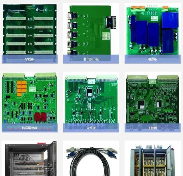
We are the world's leading supplier of spare parts for medium voltage drives of various brands

点击右上角
分享给朋友吧
GET IN TOUCH

East Sun Industrial Centre, No 16 Shing Yip Street Kl, Hongkong

Call us : +852 5261 7322

Email us : [email protected]
SITEMAP
BUSINESS HOURS
Monday to Friday : 9 am to 6 pm
Saturday : 9 am to 12 am
Sunday : Closed Support Hours in 24/7 Everyday
DISCLAIMER:
We are not an authorized distributor, reseller or representative of the following products presented on this website. All Product names and logos throughout this site are trademarks of their respective holders. Use of them DOES NOT imply any affiliation with or endorsement by them.
© 2020 robiconperfectharmony.com site . All rights reserved Site Map
