

How long will Siemens offer spare parts support for the GH180 MVD NXG NXGI NXGII NXGpro control?
How long will Siemens offer spare parts support for the GH180 MVD NXG NXGI NXGII NXGpro control?
Secure your Perfect Harmony MV Drive
Investment with the latest technology
NXGpro Digital Control System Upgrade
Industry Services
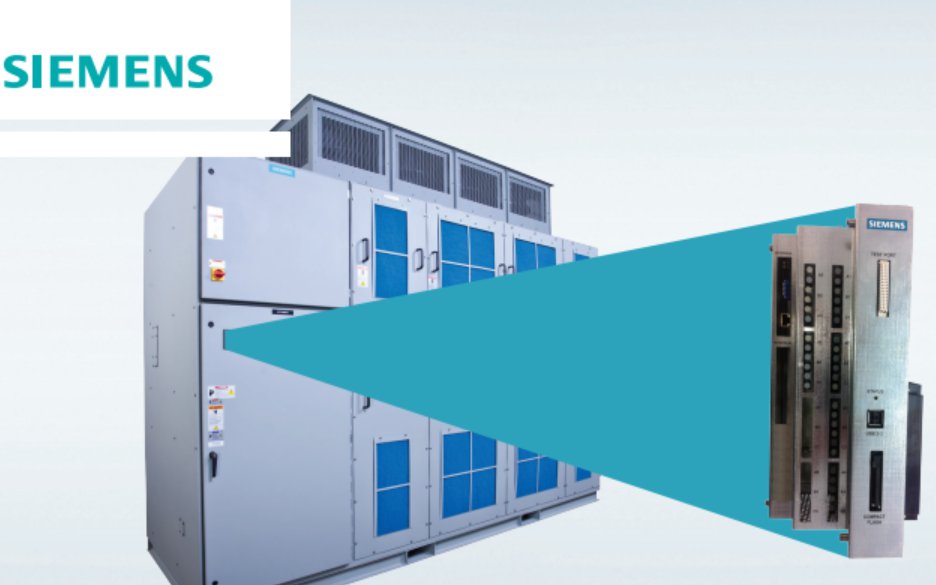
NXGpro is the latest generation of control for
SINAMICS PERFECT HARMONY GH180
medium voltage drives. NXGpro is easily
retrofitted into existing NXGI and NXGII
drives while utilizing the same software and
software tools.
NXGI/NXGII hardware and software are currently
controlling over 10,000 SINAMICS PERFECT
HARMONY GH180 medium voltage variable
frequency drives with an excellent history of
reliability. The NXGI control was introduced in
2001 and followed by the NXGII control in 2005.
NXGpro is the latest evolution in control systems
and is smaller, more powerful, reliable, and
efficient than previous generations.
NXGpro software has the same basic
functionality as NXGII but with an additional
Tamper Resistant Input Protection feature. The
purpose of this new feature is to ensure
protection of the drive by verifying that the
upstream input circuit breaker is functioning
properly. NXGpro also uses the same compiler
and operating system as NXGII, so maintenance
tools such as ToolSuite remain virtually
unchanged.
Existing drives with NXGI or older control
systems may contain parts which are no longer
available and could result in extended downtime
in the event of a failure. Retrofitting your
SINAMICS PERFECT HARMONY medium voltage
variable frequency drive with the NXGpro
control provides you with maximum reliability,
simplifies maintenance, and increases
performance. To learn more about the NXGpro
control or to discuss an upgrade program to
transition your fleet, please contact your local
Siemens representative.
The NXGpro Digital Control is standard in new drives and is also designed to
quickly and economically upgrade your existing control
This state-of-the-art upgrade
package has been developed for
your Perfect Harmony Drive to
improve its control performance
and reliability while minimizing
the issues with obsolescence.
Description NXGpro Improvements Benefits
Input Protection • Enhanced Control Feature with Tamper Resistant Input
Protection function
• Better input protection scheme through the addition of
Tamper Resistant Input Protection function. This feature
tests the timing of the opening of the contactor in the
input circuit breaker to ensure that the breaker functions
properly
Serviceability
and Maintenance
• Test board available for fast and easy test access
• Smaller footprint for easier service
• Moved flash disk for access without disassembly
• Designed to update software and firmware without special tools
• Shorter downtime for testing, troubleshooting, and
maintenance service due to improved accessibility and
the ability to quickly swap the complete unit if needed
Reliability • Reduced number of circuit boards by as much as 50%
• Reduced the number of inter board connections by as much as 80%
• Reduced active DCR electronic components and bulk capacitors by 40%
• Reduced DCR external electrical connections by 50%
• Eliminated ISA bus card edge connections that can become misaligned
• Eliminated use of ribbon cables within the control rack
• Eliminated the need for control rack cooling fans
• Built in support for redundant power supplies
• Improved reliability by eliminating and reducing
components, reducing possibilities for connection
failures, and simplifying the overall complexity of the
control system
Communications • NXGpro supports NXGI/NXGII standard Communication protocols
• Also supports EtherNet/IP™ communication protocol
• If other Communication methods are needed, please contact the
factory
• Easy transition since NXGpro is compatible with NXGI
and NXGII standard communication protocols
• Increased communication capability with the addition
of EtherNet/IP™ on NXGpro
Evolution of the NXG Control System
NXGI Control NXGII Control NXGpro Control
Benefits when Upgrading from NXGI/NXGII to NXGpro
www.usa.siemens.com/services
EtherNet/IP™ is a registered trademark of ODVA, Inc.
This brochure contains only general descriptions or performance
features, which do not always apply in the manner described
in concrete application situations or may change as the products
undergo further development. Performance features are valid only
if they are formally agreed upon when the contract is closed.
Siemens is a registered trademark of Siemens AG. Product names
mentioned may be trademarks or registered trademarks of
their respective companies. Specifications are subject to change
without notice.
Siemens Industry, Inc.
3333 Old Milton Parkway
Alpharetta, GA 30005
1-800-333-7421
Order No. CSSS-NXGP-1015
© 2015 Siemens Industry, Inc.
www.usa.siemens.com/services
Let us help you plan your migration. Our on-site service is never more than a phone call away and we’re available 24/7.
Call 1-800-333-7421 to find a local service representative near you.
The NXGpro Digital Control unit improves performance, simplifies maintenance, and enhances reliability by:
• Adding a control feature to better protect the drive
• Changing the physical design to allow faster and easier service
• Simplifying complexity of assembly and number of components
• Increasing microprocessor capability to enable future software enhancements
Common questions and answers related to the new
SINAMICS PERFECT HARMONY GH180 NXGpro
digital control system
1. Q: If I upgrade to the NXGpro, what would the impact be for my existing drive?
A: The NXGpro is designed to facilitate upgrades without changing the functionality of the drive. It enforces the use of an upstream
trip able device, which must be connected so that the drive may disconnect the main power. This is done by testing the input
medium voltage interruption time. This test must pass before the drive can operate. The customer must be able to guarantee that
their trip able device can open the contactors within 100 ms. This feature enhances protection for the drive. Contact the factory
should the customer cannot guarantee the functionality of the proper input trippable device.
2. Q: What are the primary differences between the NXGII and the NXGpro controls?
A: The NXGpro is an evolutionary change to the control for the purpose of improved maintainability and reliability. It uses the same
tools and algorithms as NXGII and does not alter the drive functionality. Most functionality is combined into a main circuit board
eliminating many connectors and cables within the controller. The obsolete Industry Standard Architecture (ISA) bus and the
associated connectors are eliminated. The Input/Output (IO) interface board is connected to the Digital Control Rack (DCR) via a
fiber optic cable which replaces a large multi-conductor cable.
3. Q: How much time will it take to upgrade the current control to the NXGpro?
A: Installation downtime varies by control version, drive configuration, and site peculiarities. A Siemens Sales representative will
work with your plant personnel to determine the actual requirements for your specific application.
4. Q: Is the software compatible with all drives?
A: Yes, the software is compatible with all NXG control-based SINAMICS PERFECT HARMONY GH180 drives with the exception of
frame 325 HA (High Availability).
5. Q: How does the NXGpro control upgrade affect the drive logic parameters?
A: The existing System Operating Program (SOP) and parameter configuration functionality will remain unchanged. Additional
parameters will be set and configuration checks are performed as part of the upgrade service.
6. Q: Will the reporting I receive from the Fieldbus/DCS system remain the same with the new NXGpro
Control System?
A: The logic and setup of Fieldbus network interfacing for the NXGpro and NXGII is the same.
NXGpro Control System FAQ
www.usa.siemens.com/services
Siemens Industry Inc.
100 Technology Drive
Alpharetta, GA 30005
1-800-333-7421
www.usa.siemens.com/services
Subject to change without prior
notice
Order No.: CSFL-NGPFQ-1016
All rights reserved
Printed in USA
© 2016 Siemens Industry, Inc.
Subject to changes and errors.
The information given in this
document only contains general
descriptions and/or performance
features which may not always
specifically reflect those
described, or which may undergo
modification in the course of
further development of the
products. The requested
performance features are binding
only when they are expressly
agreed upon in the concluded
contract.
7. Q: Does the HMI have to be upgraded during an NXGpro upgrade or is that part of the new
NXGpro control?
A: No, It is not necessary to upgrade the HMI hardware. However, the software will require an update to the latest
NXGpro-compatible versions. The customer interface remains unchanged.
8. Q: Will my staff require additional training to use the NXGpro?
A: Drive operation and drive interface remain unchanged, except for newly-added parameters and diagnostic messages. These
parameters and message additions are described within the NXGpro Control Manual and Drive Operating Instructions. Training
classes are available upon request. Please visit www.sitrain-lms.com for more information.
9. Q: When did Siemens begin installing the NXGpro digital control on production units?
A: In New Kensington, PA location, the NXGpro digital control unit has been installed on production units since January 2015. The
transition to NXGpro will occur globally via a staging process by manufacturing location and product variation.
10. Q: Why does the NXGpro not support the SINAMICS PERFECT HARMONY GH180 frame 325 HA
(High Availability)?
A: The SINAMICS PERFECT HARMONY GH180 frame 325 HA is system approach to facilitate the utmost availability. Although NXGpro
does provide enhanced reliability via hardware changes and reduced components, Siemens is studying control options for frame
325 HA to ensure maximum availability and redundancy. At this time, the frame 325 HA will continue to be provided with the
NXGII control.
New diagnostic messages enforce the use of an upstream trip able device, which must be connected so that the drive may
disconnect the main power.
11. Q: How long will Siemens offer spare parts support for the NXGII control?
A: Siemens has planned for a minimum of 10 years (up to 2024) based upon the historical NXGII usage rate and current business
plans. An NXGpro upgrade will be available to extend the life of the product and to add new functionality.
"Ready-to-run" signal is not given
We have three Robicon Perfect Harmony GENIV 6.6kV drives in our gas plant, driving export compressors.
Since commissioning we have been having several problems on cell control boards ( "cap share fault"); power supply units (" power supply" or "hall effect pwr supply") and system I/O cards.
Most recently we have this problem that one of the drive does not give out the ready-to-run signal to the compressor PLC. The red LED on the I/OB board does not light when every thing is done including switching the MV power on. We tried to put a jumper to make a "fake" signal and the compressor started well. I have no idea what could be the reason.
About the other problems you may please also share how we can permanently solve them like:
- Are cell control boards repairable? ( we have more than 10 which we replaced after the "cap share" thing.
Thanks for your time.
Hi,
I think you need check the SOP, you can confirm the I/O is faulty or not, or change the I/O location.
Hi Mfuachuma,
Cell control boards are repairable. Once repaired they can be tested inside a cell on the bench using a cell tester.
Individual Cell Load Test Video
Other PCBs such as system IO, system interface are also repairable. Once repaired they be bench tested using a drive simulator.
Drive Simulator Video
will4
Thanks AutoGen! I will try this one out.
It also happens that one we jump this signal and start the compressor, the compressor will start okay but will trip on "cell... DC BUS OVER-VOLTAGE" fault after short time, say 10 minutes or during stopping after test-running for short time. The fault occurs randomly on different cell at each attempt. What could b e the cause of this?
Thanks in advance!
Start permissive should be high
Respective I/O should be functioning
Cause for DC Bus over voltage as below
1. For Dc bus over voltage issue, this can be due to high input voltage to power Cell. Your power Cell moght be reated to 750Volts AC. When input voltage to power cell raises you face DC bus overvoltage.
Remedy: Input transformer tapping can be moved to -5%
2. when you are ramping down very fast.
Remedy: You can increase deceleration time to avoid DC bus overvoltage during ramping down.
Thank you Mohammed! Especially with the DC BUS OVER-VOLTAGE issue, I think in our case the second point (ramp down time) was the problem. Will look int it.
GH 180 Int AI 2 read value configure to Register Data from Drive
Dear Expert,
In our GH 180 communication manual, If I want to read VFD int AI 1 or 2 value in network data, I can configure as Man ID 3502 to one of the drive parameter(Data from Drive 24). See more details in attached picture. However I can't able to read any values. I am not so sure that I am doing right? Could anyone experiences on such matter?
Reagrds,
Peter
Hi Peter,
Did you check the screen in the Debugger software that shows the Analog input values? Is this showing zero as well for Analog inputs 1 and 2?
Regards,
will4
Dear Wil,
Yes, I can able to see the Int AI1 and 2 values. Please see attached photo. Another questions, Man ID 3502 is configure for WAGO AI1, I mean external AI?
Where is the NXGpro Control Manual available from?
A5E33474566A_AB_ NXGpro Control Manual.pdf
GH 180 NXGII SOP
Dear Colleagues,
When a VFD experienced a Fatal fault, How does the VFD behave? Is a coast stop or Ramp Stop? I think it is coast stop, Is there a way to configure in SOP as a control stop(Ramp Stop)? If I will write the below statement in SOP,
RampStop_O = FatalFault_I + RemoteInhibitTFlag:
So VFD will behave a ramp stop when the fatal fault happened. I seek for the advise. Thanks,
Regards,
Peter
Hi Peter,
I am not sure its good practice to try and keep the drive running or ramping down after a fatal fault or trip. This could cause damage to the drive or worse personal. However you could try out your logic safely on your PH NXGII simulator kit. From my experience the drive should coast regardless.
Regards,
will4
Gh 180 NXGPro Parameter set up
Hello Experts,
Gen IV NXGPro drive came with 15 cells with advanced cell bypass options. What is the right parameter set up for parameter ID 2541(Permitted minimum cell count)? I want to allow maximum 3 cells to bypass in the system? So should I set ID2541 to 12? Is it right?
Regards,
Peter
Hi Peter,
Setting the minimum cell count parameter to 12 should achieve your desired functionality. To verify it works with the drive running pull out 4 fibres from the DCR rack. The drive should trip when the fourth fibre is removed and not be able to be restarted.
Regards,
will4
GH 180 NXG Pro Drives Profibus configuration
Dear Experts,
In Perfect Harmony GH 180, Is there a way to send the following data(ID 8020= running hours and ID 8050 = Output KWH) to DCS via profibus? Could you please help me?
Regards,
Peter
Hi Peter,
Unfortunately running hours and output KWH are not available as either a pick list item or output data ID (I checked in V5.4 NXG firmware). As an alternative you could use input MWHr which is manual ID 3668. For the running hours you could write some code into the DCS side that looks at the drive running indication and keeps a track of the hours.
I have attached the NXG communications manual for reference.
NXG Communication Manual A5E02924901A_AC.pdf (530 Downloads)
Hello,
Help to choose a replacement for this product.
LDZ: A1A094091 450A, 690VAC, 6,9 gRB 72 D11A 450
This looks like a Mersen fuse with catalog number PC72GB69V450D1A and item number Q302671.
Datasheet here
Thanks, But I need Siemens catalogue number
NXG Pro TRIP
Hello,
I commissioned NXG Pro drive at customer factory and it ran without problems till December. I found defective Profibus card and after I exchange it I cannot run the drive. It shows no fault, no alarm and it is possible to run, nor in automatic, nor in hand mode. I checked also all fault and alarm flags in debug tool, there are all in 0. Drive only shows "TRIP" in MODE line on display. What does it mean? It is TRIP fault, described in manual? In control manual there is no TRIP message in list for MODE line.
Drive is controlled via Profibus from Simatic (Speed demand, Start and Stop). There is second drive, also controlled via same Profibus line and it runs good. No BF or SF faults on CPU, and I hope same control sequence for both drives.
Thank you for any idea
With regards
TRIP means Tamper Resistant Input Protection.
It is always needed during first commissioning to run this tet once just to chech if the medium voltage CB is working properly if the drive send the command OFF to that CB.
More information you will find in the attached document: "NXGpro Introductory note 4 V2 - TRIP status".
Probably the second problem in your case is that the drive does not remember that this test had been once already during first commissioning (to replace the PROFIBUS card you had to switch off the control supply and the settings on CF are gone). It is a known firmware bug. In that case you need to orfer new CF card with FW6.3 from US.
Attachment
NXGpro Introductory note 4 V2 - TRIP status.pdf (254 Downloads)
Thank you very much for your help, Motorek! After your recommendation I succeeded to start the drive after successful test of input breaker.
During commissioning I didn't proceed this test. It was my first commissioning of NXG Pro drive, I didn't know about this test. And the drive at the time of commissioning didn't ask for this test, although it has Drive Has Input Breaker parameter set to Yes.
I have to ask support for new version of software to fix this bug.
Thank you very much
With best regards
As of NXGpro software version 6.3 the TRIP display for Tamper Resistant Input Protection has been changed to IPIT (Input Protection Interruption Time) as the TRIP acronym was misleading.
Fault IOC because problem system I/O board?
We are having, here in at our plant of Brazil, frequent failures by IOC and Overspeed (mainly on 10/10/2016 and 05/10/2017) in SIEMENS / ROBICON PHGH180 / GEN3E Frequency Converter.
The Motor voltage = 6600 V and Full load current = 294.8 A
We have not come to a conclusion about the cause.
We change the system I / O and the equipment returns the operation but the premature failure is doubtful if it is the real cause of the problem is something with respect to noise, grounding and the System I / O board.
The following are the logs of the last fault and the register of pick zero sequencie voltage.
Is the faulty system IO board still installed? Are you able to go online with the Debugger software and read out the system IO board firmware? Revision BK system IO boards showed this impossible jump in motor speed resulting in either IOC or overspeed. The firmware needs to be V2.11 or higher to fix this.
Our Version of firmware at this drive is 5.2.2.
The board system I/O we change at oct/2016 have the PCA/Firmware A1A10000423.00 REV.BH and the board installed at oct/2017 PCA/Firmware A1A10000423.00 REV.BN.
The register data view a peak of voltage zero sequencie at moment of last fault.
I would do a visual inspection of the complete circuit from output current sensors to modulator board. The location of the current sensors is in the Input / Output Cabinet of most Harmony Drives. The sensor outputs are wired to the signal conditioning board, then to the system interface board. On the system interface board is the circuitry for deriving the threshold level for the total current. This signal is wired to the Modulator Board that contains the DAC and comparator circuitry. Potential issues that affect the fault performance include;
- Incorrect IOC setting in the menu (Menu ID 7110)
- Incorrectly sized Hall Effect sensors for Drive rating
- Defect in circuitry on the Signal Interface Conditioning Board, System Interface, or Modulator Board.
Check the wiring between the boards including the shielding. The modulator board would be the next board to replace.
Robicon PH profibus
Hi everyone,
I'm looking for manuals or anything about a Robicon PH communication via profibus dp to a S7-400 CPU. I'm sorry if it's too basic, but I just can't find anything about it. I suppose there is a GSD file to configure it on HW configuration on Step7, isn't it? If u have this file I would appreciate if u post the url.
Best regards
Please find the communication manual in the link below
Section 6.7 talks about the GSD files.
Note: The Profibusmaster must be configured to have the same quantity of Bytes that are set by the parameter ‘Network I/O Size’ (9951) to communicate with the Siemens NXG drive.
Attachment
NXG_Communications_manual_A5E02924901A_ver_AA.pdf (942 Downloads)
When you install Tool Suite the gsd file is part of the installation. For example;
C:\Program Files\Robicon\Communication Files\Profibus
Note DeviceNet and ControlNet eds files are also installed.
How received "profibus from drive" data must be scaled at PLC?
ROBICON Communication board
Hello,
We are having a hard time to figure it out which communication board our ROBICON inverter is using, i don't have access to it right now, so i thought that i could find out the exact model reading the GSD file (ROBI0868.GSD), but no luck. We need to buy spare parts to lessen any plant downtime due to failure in the CB.
Any help will be appreciated to help me in this quest. Is there any online catalog or documentation that might help me?
Thank you for your attention.
Hello Indiaum;
First, here is a Robicon NXG catalog for Liquid Cooled droives, and a screenshot of the communication optional cards (see below)
https://www.industry.usa.siemens.com/drives/us/en/electric-drives/medium-voltage-drives/Documents/DRV-MV-liquid-cooled-catalog.pdf
And this thread discussing Robicon Perfect harmony Profibus has a lot of information you can look at, especially the communication manual:
https://support.industry.siemens.com/tf/WW/en/posts/robicon-ph-profibus/103590?page=0&pageSize=10
Hope this helps,
Daniel Chartier
Hi Indiaum,
For the Robicon communication PCB there are a few different generations. Assuming you are using either a NXGI or NXGII controller there are three different generations of communication PCB. The latest generation board has a part number of A5E03407403. In addition to the communication PCB there are Anybus modules that sit on top of the communication PCB. These differ depending on which fieldbus you are communicating over. Since you are using Profibus the Anybus part number is A1A252241.155.
Other Anybus part numbers are as follows;
DEVICENET PROFILE12 - A1A252241.156
MODBUS ETHERNET TCP - A1A252241.157
CONTROL NET - A1A252241.158
MODBUS + - A1A252241.159
MODBUS RTU - A1A252241.160
ROBICON Perfect Harmony GenIV Opening GCB at close
Hello everyone.
We have a total of 10 ROBICON Perfect Harmony gene. IV, manufactured in Germany in 2010. (6100v; 355A) model 6SR3102-5FJ44-0BGO-Z.
Every time we open the 6 Kv switch for some maintenance we have trouble closing it again. The VDF before sending the closing order to the GCB is without alarms. When we send the order to close the switch this closes and reopens by an order of the VDF itself, (the protection of the GCB does not make the shot). At the second or third attempt to close the switch is closed, but this operation is good for the teams and we need to solve it.
Has anyone had the same experience?
Thank you very much from Spain.
Hi Miguel,
Do you have a copy of the drive system operating program (SOP)? There may be some logic written in the SOP around the interface between the drive and the upstream breaker. Also check the status of the latch fault relay LFR before attempting to close the upstream breaker. It never hurts to turn the LRF reset key switch to ensure the LFR is not in a latched state.
Good afternoon. There is an old drive Asi Rubicon, you need to know the date of production. On the door there is the date code 0539. Means the date of production 2005 39 week. I understood everything correctly.?
Hello jdn,
I saw on ASI Robicons (made in USA) date codes 0403 and 0350, but also I have no information about year of manufacturing. But according to your code it seems you have a right, that there is year and week of manufacturing.
Italian Robicons have year of manufacturing directly on drive label...
With best regards
Martin
We have a ROBICON GENIIIE HARMONY VFD equipment in Cartagena Refinery in Colombia, and this equipment has defined “Integral Gain” parameters. However, we don’t know what is the units for this parameter: resets per minute, resets per second, seconds, …
You answered me: "We use resets per second. The term is represented by 1/time, so the larger you make time, the slower the integrator will react."
However, I still have the following doubt: you say that you use resets per second, but you also say "so the larger you maketime, the slower the integrator will react".
Our New Question:So the larger I make "integral gain" parameter (represented by 1/time), ¿the faster the integrator will react? (since time is inverse to the “integral gain” because is represented by 1/time).
Hello Haider;
The implementation of PID (or PI) controllers varies amongst the different manufacturers, which can lead to some confusing discussions.
What you are looking at right now if the dichotomy of Reset Time (in sec. per repeat) versus Reset Rate (repeats per second). In this context, "reset" refers to the time given to the integral component to match the action of the proportional part of the control algorithm. So the smaller the time allowed (or the larger the rate, since it is the inverse) the stronger the integral action.
One great ressource I follow for PID controls is controlguru.com. The following extract can appear trivial, but start following the links and you will soon discover a lot on cntrol theory, as applied in PLCs:
Reset Time Versus Reset Rate
Different vendors cast theircontrol algorithms in slightly different forms. Some use proportional band rather than controller gain. Also, some use reset rate,Tr, instead of reset time. These are simply the inverse of each other:
Tr = 1/Ti
No matter how the tuning parameters are expressed, the PI algorithms are all equally capable.
But it is critical to know your manufacturer before you start tuning your controller because parameter values must be matched to your particular algorithm form.Commercial software for controller design and tuning will automatically address this problem for you.
With your answer I understand that, because the Perfect Harmony parameter is in resets per second (1/time), So the larger I make "integral gain" parameter, ¿the faster the integrator will react?
Note: The Perfect Harmony does not work with Ti (reset time), only with proportional and integral gain parameter.
Hello Haider;
I do not have the manuals for Robicon drives.
But if integral gain uses time units (e.g. seconds), the larger the integral gain (the more seconds you allow for the integral action to act on the elimination of the error in the control algorithm) then the slower your integral action becomes... Think about it.
Hope this helps,
Daniel Chartier
Trending and Anaylsis Software for GH180 Perfect Harmony Drives
A GH180 Perfect Harmony medium voltage drive interface has been developed for the iba high speed data acquisition system. No configuration or setup is necessary on the drive side with up to 90 signals trended per drive. 50ms sampling and no additional hardware required. All drives sit on the same trend window for load sharing analysis etc.
A very powerful tool for commissioning, fault finding, performance monitoring etc on the Harmony drives.
Sample dat file and iba Analyzer software can be downloaded from link below
https://www.dropbox.com/s/iqc30p16fu58nft/ibaSiMVD.zip?dl=0
Hi will4,
could you please add some more details about this facinating possibility. I would like to use it in my daily work.
But how can I acuire the data files for thi analyzer sotware? Could yoy describe the way how to connect the NXGII. It is possible to see the trends in online or only in offline mode?
Why the sampling time is limited to 50 ms ? It seems to be to slow for tracing.
Best Regards
Hi Motorek,
The data is available both in live or historical form. To see the live trends you use the ibaPDA software. Have a look around the iba site to get more information on ibaPDA and other products such as HD server which can all be used together with the GH180 interface. The manuals and documentation for this interface will be available shortly with the interface part number being 80.004180. Sampling is set to 50ms as it is all Ethernet based acquisition hence no requirement for extra hardware as we use the standard Ethernet port of the NXGII single board computer. All you need is the IP address of the drives you are connecting to. Once you use this software you will wonder how you ever did work without it.
Attachment
Interface-SiMVD_v1.1.pdf (159 Downloads)
Perfect Harmony-China production
Hi,
Does anybody has Perfect Harmony drives Transformer plate information?
I have 4 drive from Siemens China and they don't provide the plate information, only drawings.
Thanks
Hi
What is your drive name plate?
Trafo design depends on your drive rating, incoming voltage, number of power cells etc. A typical example for 13.8 KV VFD with 9 power cells will be as as attached.
Vijay
Dear Vijay,
Thanks for the example.
Where did they produce this transformer?
Best regards,
apesky
Hi
Normally NWL factory @ USA
Vijay
Please find the attached Trafo details of the 11 KW - 24 Cell - Gen IV - NXG -II - Siemens China - PH-VFD .
Thanks & Regards
SWA1989
Attached Transformer Name Plate for PHGH180 China Manufactured Year 2006
Hello,
Is there a way to test the bypass system? It´s a 6SR3502-6HC38-7AJ0 drive.
Thanks in advance.
From the manual;
Perform this test only if the Drive is equipped with Mechanical Bypass Contactors.
Stop the drive by giving a STOP command.
Once the drive is in the OFF or IDLE state, change the Control Mode (2050) to Open Loop Vector Control
ENABLE Fast (cell) Bypass (2600). Access this parameter through Drive -> Cells -> Fast Bypass. Also make sure that in the Cells submenu, the Min. Cells/Phase Count (2540) is set to be one less than the installed rank of cells.
On the keypad, select Bypass Status (2620). The display should show all “A” (available) characters. The order displayed is A-phase (1 through n), B-phase (1 through n), and C-phase (1 through n), where n represents the number of cells per phase.
Pull a fiber-optic link for an A-phase cell (e.g., A1) out of the fiber-optic interface board. Check Bypass Status (2620). It will now display a “B” (bypassed) character in the location for the cell
that the fiber was removed from.
Repeat steps A and B for a cell from each of the other two phases (e.g., B1 and C1). Re-connect all fiber-optic links to their corresponding cells and reset their bypass status using Reset Bypassed Cells (2640).
Repeat steps A through C until all bypass contactors have been verified. Make sure all fiber-optic links are connected back in the correct order before moving to the next step
Hello,
I have a Robicon 454 GT drive which does not stay in Auto Mode after power loss to the drive.
Drive goes into Off Mode anytime there is a power loss, I must push the Automatic button on the keypad to make the drive go into Auto Mode.
This problem started after microprocessor board replacement.
Any suggestions on how to make the drive stay in Auto Mode?
Where I can download tool suite nxg of robicon perfect harmony IV gen?
Tool suite is a free software and normally a CD also shall be availble with your local Siemens support centre.
Regards,
Vijay
U can download toosuite from siemens web site. It comes as a package for Drive tools, SOP utilities...
Regards,
VK
The best solution is to ask whoever provides you with service, or to lodge a support request at https://support.automation.siemens.com/
Robicon panel VFD room:
Preset hour meter 8030 Function need password,
I entered 7777 but no thing happen, Can you help me to preset my running hours because I lost all
the running hours.
I just tried this using Tool Suite V 5.1.0.1 and drive control software 5.3.0 12-6-13. After entering the access level 7 password I was able to preset the elapsed time, input kW and output kW hours consumed.
Are you using Tool Suite or going through the keypad?
I am using the keybad
Try using Tool Suite. If you don't have it you can download from the link below
Good day.
The problem with ROBICON GENIIIE 6000V 4MW with compressor application.
Motor load current-283A, voltage - 6000V, Motor kW Rating = 2800.0 kW
After the command "upTransferRequest_I" recieved, drive successfully synchronized and I have got "IOC fault" simultaneously with command "upTransferPermit_O" from VFD . System commissioned several years ago, and their were no problems earlier.
By increasing parameter ID1050 to 350A problem is temporarily solved, drive starts motor properly and successfully transfered to line contactor.
After that fault occurs I checked:
- phasing sequence
- synch transfer status
- hall effect sensors (+15 -15V)
Everything is well. Does anyone have any idea what should I check else?
Manythanks
NXGpro is the latest generation of control for SINAMICS PERFECT HARMONY GH180 medium voltage drives.
Find some questions and answers regarding the new controller attached.
NXGPro Upgrade Questions.pdf (134 Downloads)
Dear Users,
We are in a need of developing a test station for induction and synchronous motors testing. Maximum power of a motor that is to be tested is 500kW at voltages from 400V to 3.3kV. Is it possible to use SINAMICS PERFECT HARMONY GH180 for this purpose? Can we use only one power cell per phase when testing 400V motors and all three power cells per phase when testing 3.3kV motors, or it is possible to bypass power cells only in a case of failure of one of the power cells?
Is it possible to combine different power cells (different amperage) and use three 720A power cells when testing 400V motor and three 720A and six 315A power cells when testing 3.3kV motor?
Thank you in advance.
Best regards,
Antonio
Hi Dule7777,
You can operate a GH180 drive at a lower than rated output voltage and the required 100% motor frequency continuously no problem providing the cell current rating is sufficient. Therefore running a 400V motor in V/HZ mode (not sure about SMC mode) on a 3.3kV drive in theory will work along as the drive accepts the non standard or LV motor parameters. The cells in the drive always contribute evenly to the drives full range of output voltage assuming there are no cells bypassed so there is no need to remove cells etc. In terms of harmonics it makes sense to leave all cells in the drive. If you are wanting to use different numbers of cells in the same drive ie 3 or 6 per phase you will need a input transformer with the secondary windings to allow for this which is not really practical. Get confirmation from the factory but a drive with 630V 720A cells (you may require 4 per phase) should be possible for your application.
Hi
As expert advised, you can parameterize the MOTOR menu and LIMITS menu like motor trip voltage
ID 1160 with respect to motor name plate.
No need to bypass any cells. VFD will automatically adopt output voltage accordingly.
I commissioned one of the pump testing stations in OLVC with different parameter sets.
Alternatively you can use frequently used motors with different file names and can use to open through Tool Suit before running. I mean 400 V motor under one file name, and 3.3 KV motor under another file name.
Thanks
Vijay
Previous : Siemens Robicon GH180 MV Drives DC-Link Capacitors Refurbish, Repair, Replace
Next : GH180 NXG Firmware NXGpro NXG controller Tool Suite Latest Version


 Copy product links
 Long by picture save/share
INQUIRY


Add Successfully
We are the world's leading supplier of spare parts for medium voltage drives of various brands

点击右上角
分享给朋友吧
GET IN TOUCH

East Sun Industrial Centre, No 16 Shing Yip Street Kl, Hongkong

Call us : +852 5261 7322

Email us : [email protected]
SITEMAP
BUSINESS HOURS
Monday to Friday : 9 am to 6 pm
Saturday : 9 am to 12 am
Sunday : Closed Support Hours in 24/7 Everyday
DISCLAIMER:
We are not an authorized distributor, reseller or representative of the following products presented on this website. All Product names and logos throughout this site are trademarks of their respective holders. Use of them DOES NOT imply any affiliation with or endorsement by them.
© 2020 robiconperfectharmony.com site . All rights reserved Site Map
