

SINAMICS PERFECT HARMONY GH180 GenI/GenII/GenIII/GenIV/6SR5, NXG Controller Tool Suite v 6.3.2.1
SINAMICS PERFECT HARMONY GH180 GenI/GenII/GenIII/GenIV/6SR5, NXG Controller Tool Suite v 6.3.2.1
information of individual power cell tester
Hi Will,
Can you provide more information of individual power cell tester information? I also want to construct a same one. I have PH NXGII simulator kit, Variac and power cell tester. Appreciated your help. Thanks,
Regards,
Peter
Hi Peter,
Siemens have a Portable Harmony Cell Tester (PCT) (P/N 469939.00). This allows you to operate the power cells on the bench outside of the drive. You can connect up a reactor to the power cell output and load test the power cell. With the PCT you can read back all the alarms and faults and cell temperature. The software used is called "1cell".
It is possible to construct your own cell tester as I have. My design is based around a Xilinx FPGA. It offers the same functionality as the Siemens PCT.
Regards,
will4
Hello good afternoon, the reason for my message, I was given 6 load cells to verify in the laboratory, I want to know what I need to do a test like the one you did in your laboratory, so you used a three-phase transformer, a converter from optical fiber medium to rs485 to connect it to MICROMASTER Vector? I just want to know if I'm right, I currently have the cell, the oscilloscope, the three-phase transformer, I need the fiber media converter to rs485 and I just bought a MICROMASTER Vector, you have a schematic rod to see how I would connect it and do a test of the cells, it should be mentioned that I was checking the electronic elements and found variation in the resistances that are in series of the cell, I would like to know if these variations are normal.
As a minimum you need a Siemens Portable Harmony Cell Tester (PCT) (P/N 469939.00) or equivalent and a 700VAC power supply. This will allow you to operate the power cells on the bench outside of the drive. Without the portable cell tester there is not much you can do apart from send the cells out for test or repair.
OLTM Mode
Hi,
I am about to make the commissionning of VFR ROBICON PERFECT HARMONY NXG IV ,
How can i access to the OLTM Mode. Can anybody help?
Korbice
Hi Korbice,
OLTM is found under parameter 2050 - Control loop type.
Regards,
will4
Thnak you!
But is it Normal that i can not access it through DRIVE PARAMETERS in the HMI ?
When select Drive Parameters (2000) and then press Enter to get to the Submenu, I get nothing but
Parallel system (2051) Disable. Is that Normal because they have hidden the other submenu functions?
Thanks Will,
OLTM done, i have checked all the input signals OK except the speed demand not available yet so i have done on local mode , but no DRIVE READY TO RUN (Lamp always OFF)
Thanks
Breakout IOB different part numbers
Hi
What is the difference in below part numbers of Breakout IOB. Is it firmware related and both can be swapped or they are different voltage levels... etc. . Please confirm. Also is there any list/link of recommended spares for WCIII and GEN IV , VFDs
A5E01649325
A5E01649374
Thanks in advance
N Vijay
Hi N Vijay,
For the I/O breakout board;
A5E01649325 = 120V I/O
A5E01649374 = 24V I/O
For the list of recommended spares have a look in the respective drive manuals. Normally near the back is an appendix with the recommended spares list.
will4
DRCTRY.PWM
Deionizer part numbers
Hi
What is the difference between the below two deionizer tank part numbers. We have the VFD with name plate as attached. Which one we should use. Thanks
6SR3950-0SM03-0AD0
and
6SR3950-0SM05-0AD0
Diagnostics Create fault and Reset
I have Created a fault in a particular Cell using diagnostics feature of Tool Suite 6.3.2.1 . Fault occurred, now when I reset the fault, it doesn't get reset. In the fault it says forced cell fault. Please tell me how to reset it without turning off control or main power supply.
Resetting Bypassed Cells
The NXGpro software provides a mechanism to reset bypassed cells to work in conjunction
with the Force Cell Bypass function, if it is used for testing purposes only and no permanent
cell fault exists. This function is labeled “Reset bypassed cells” (ID 2640) and is set to Level
7 security. It cannot be invoked while the drive is running.
Note
Resetting bypassed cells should not be used for cells that have actually faulted in operation.
How can downald program?
Hi will,
Our collègue make factory rest by mistake the problème we dont have backup in our pc for this but we have 3 others drive same how can downald program,i need your prompt help
Thanks
Dears,
I downald from other drive cfg file and i chnge only the modbus adress and tcp/ip also the drive is ready for opération .I wanna to know if the SOP program is including or not if not how to configure it.
Regards,
You will need to download the SOP file in addition to the parameter cfg file. To do this in Tool Suite navigate to Configuration/System Program/Download System Program. Select the relevant compiled SOP file and download. After downloading the SOP you will need to select it and make it active by using parameter 9146 -Select system program. You can verify the chosen SOP is active by navigating in Tool Suite to Configuration/System Program/Display System Program Name. The SOP highlighted in bold is the active SOP.
Hi yass81,
In Tool Suite for older versions of firmware to save the parameters you needed to select Configuration then Save Data. For recent versions the Save Data is done automatically. Maybe the parameters were not saved and the control power was cycled?
Regards,
will4
Hi Rob a client has request that I assist with the commissioning of a mill, the specific philosophy that he wanted is listed below, I have prepared a logic below to be programmed into the SOP to assist his request, please if you agree that this will work.
When we swap between the speed profiles, please confirm if it is required to stop the VSD and to start again before the new speed profile can be accepted.
I have added some code below to get your opinion on, will I have to stop the DRIVE or can we swap between the two forward speed profiles?
We did a 4MW MILL VSD in Zambia 2015 with a GEN 3 which followed the same start-up curve pattern as requested, The client generated the speed demand in the PLC as per the profile required.
Will the code below satisfy the requirement and what do I have to add to the SOP?
I do not have the SOP, I have requested it but got the reply that it is a standard SOP, the drive is already on site so I will only access to it after arriving on site.
*****
T 16 (10) = Runrequest_I
Output_1 = T 16 (10)
Speedprofile_2 = Runrequest_I * /Output_1 ; 3Hz speed Par 2080
Speedprofile_1 = Runrequest_I * Output_1 ; 50Hz speed Par 2070
Runrequest_O = Runrequest_I * /Output_1 * speedprofile_2 * /speedprofile_1 ; 3Hz speed Par 2080, Par - 2290 ( 2Sec) , Par 2300 ( 2sec)
Runrequest_O = Runrequest_I * Output_1 * /speedprofile_2 * speedprofile_1 ; 50Hz speed Par 2070 Par - 2270 ( 60Sec) , Par 2280 ( 60sec)
******
CLIENT REQUEST:
Hi Jaco,
For the Mills start-ups we are looking at the following scenario on these Mills due to the Siemens Mill Controller Locked Charge Detection not being able to be commissioned at this time. You will be co-ordinating with our Mechanical Engineer (Joseph Fiamingo) and Electrical Engineer (Jeremy Philip) along with the customer to achieve the final Mill start-up procedure.
Siemens technical department are happy to work closely with Saftronics to monitor the motor current amps to determine if it's possible to start the mill each and every time at approximately 3hz (5% motor speed) for at least 1 revolution.
If the above can be achieved, Outotec will be satisfied with the following options;
Option A - Implement slow ramp up procedure as per above for each and every start and remove the 30 min timer we use on the Control Philosophy.
Option B - Keep the 30 min timer active in the philosophy and within the 30 min window, implement a normal 30-60s ramp-up. Only after the 30 min lock charge timer has been activated apply the slow start up procedure.
If the above slow ramp up is not possible, then the Mills inch drive units will need to apply (i.e. after 30 min timer).
Your guidance is appreciated.
Jaco Louw
Hello. Is there a more detailed maintenance plan than the chapter provided in the manual for these? I'm looking specifically for the annual inspection and cleaning of the Control and power I/O cabinet.
Thank you!
Hello heatherlelane;
Siemens proposes a checklist for annual maintenance of the Perfect Harmony drives in the following link; you can use the North-American telephone number suggested:
https://support.industry.siemens.com/cs/us/en/view/35772200
Hope this helps,
Daniel Chartier
I called this number and was told I needed to speak to a technician and haven't heard from anyone. Can it be emailed?
Hello heatherlelane;
I have no further information, but only a suggestion. The link proposed was quite old, at the time Siemens purchased Robicon drives. The Perfect Harmony drives should have been integrated in Siemens Support since then. So you could try a Support Request, the question posted there should make its way to a Robicon/Siemens tech that would then contact you back.
You will find a link to Support Request at the top of this page.
Hope this helps,
Daniel Chartier
Hi
We have WCIII Robicon VFD. Recently tank level went low due to water leak from one of the cell hoses at inlet start point . Fault logs are attached herewith.
Part of SOP is as below
In the drive SOP it is being generated by INTERNAL FLAG
$TankHighLevel = UserFault44_O;
UserFault44Wn_O = TRUE;
TankHighLevel = InternalNetInFlag35_I;
UserText44 = "Coolant Tank High";
My question is why the drive should read tank level high, while it tripped on Tank low low/ MV TRAFO OT (over temperature)
Regards,
N Vijay
Good Morning
I would like to ask the datasheet of power supply for robicon´s VSD. The part Number of this Power supply is 6SR0960-0CD01-1AD0,I have tried to search on internet but I didn’t find. there some one can help me??
The datasheet for this power supply - XP Power F7E1A6G2 is attached.
Hi
One of our WCIII VFDs reading input KWH in reverse direction. Only difference between this VFD and other VFDs is that drive efficiency is showing 100% unlike other VFDs where it is showing 99.4 % or 99.6%
Our monthly reading is being noted down by power consumption group and found as below. How to get the correct reading
Thanks
N Vijay
NXG Tool Suite 6.4.1
Hi Dear Experts,
I am commissioning a 315 kW GH180 drive, but there is profibus control problem. PLC can read datas from drive but it can't write any datas to drive. I have to add a line to the sop HEX file like this "Network1RunEnable_O = TRUE".
So I need tool suite v 6.4.1 but I can't find anything. Please help me about this issue.
Thanks.
Dear sir,
Did u find the toolsuit pro..pls suggest link to download..
Thanks
you can do it with 5.4 also.
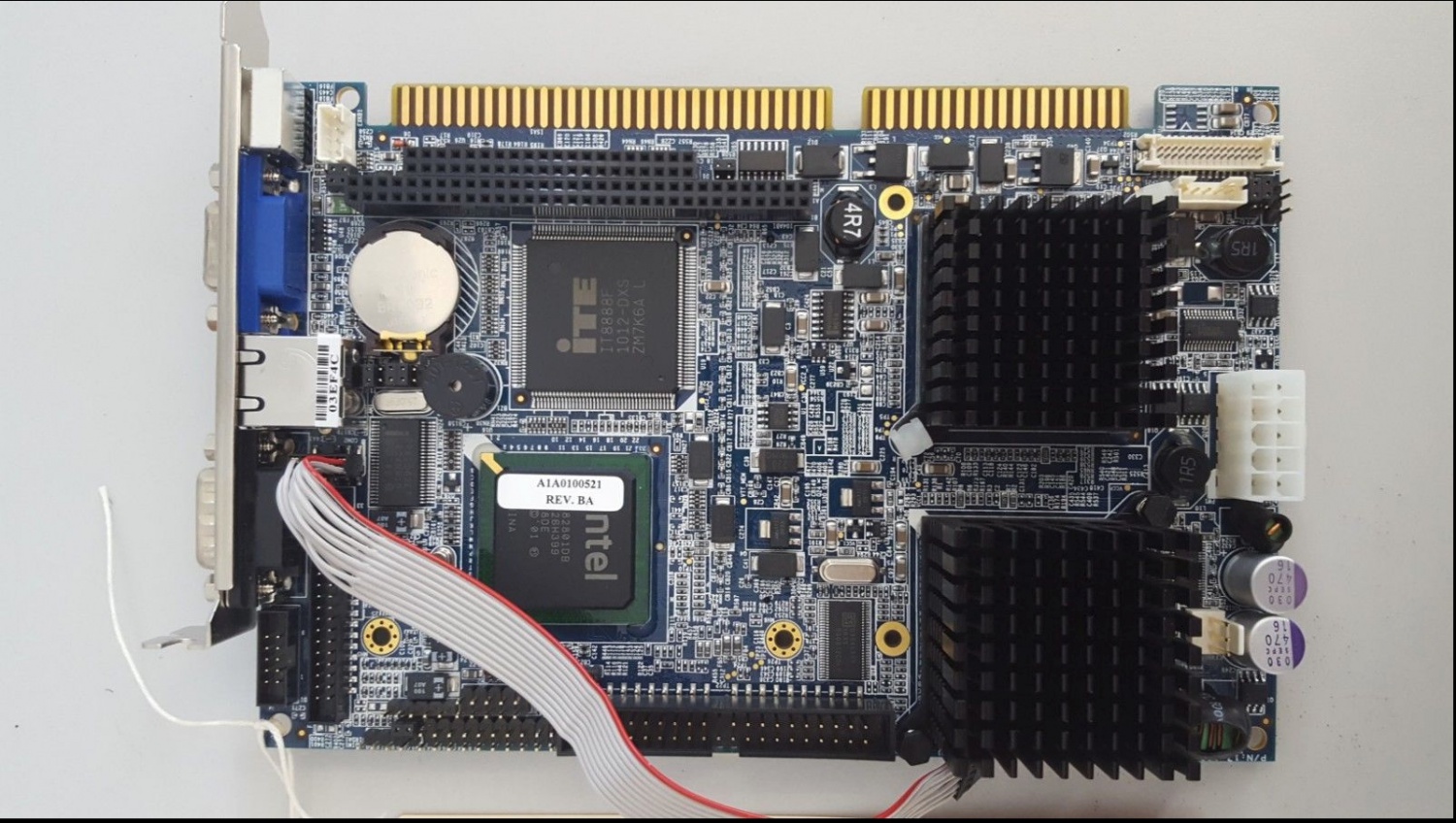
Have you tried a new Single Board Computer in the drive control rack? Move the compact flash card from the old board to the new board.
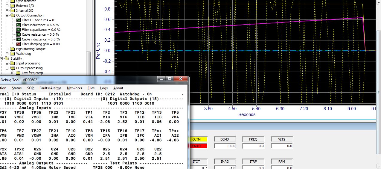
Output reactor heating up
Hi everybody
We have working a VDF Robicon perfect harmony NGXII (900HP / 4160volts) for a pump with cable distance about 4500 meters.
The drive has installed a special output reactor dimensioned for that distance.
The reactor has a high temperature, about 130°C. It is keeping in that value.
The current consumption motor is lower than the VFD’s capacity.
Is this temperature normal? why the output reactor is heating up?
In the electric diagram the adjustment of the sensor is at 170°C for the alarm and 190°C for the trip.
Thanks for your comments.
Dear Sir,
Can any body tell us where we can purchase Tool suite Version 5.XXX for NXGII
Is there any legal source for tool suite.
How we can download or purchase.
what are the formalities required .
thanks in advance...
Hi guys!
I was looking for new spare cell control boards and I specified Part Number A1A10000432.72M - ( Same as what we have installed in our drives).
Now the supplier has brought me the boards but with Part Numbers A5E34621797072, and he claims that Siemens have recently changed the part numbers.
Just curious whether this information is correct (the boards look similar); and if that is the case, is the said part number the right replacement of the old ones I have i.e. P/N: A1A10000432.72M.
Thanks!
I see in a previous post you are asking about running a motor that is rated much higher than your drive rating. The parameters you uploaded reflect this also. First thing I would say is that the motor and drive should be sized correctly. You may be able to get this setup working however its definitely not a good way to operate. Some questions/comments;
Was this drive running previously with a correctly sized motor?
The drive parameters dont look correct for output voltage and current.
The input and output attenuator sums along with CT turns need verifying against the drawings.
I would put flux control, speed loop and current loop parameters back to factory defaults. These parameters dont typically require changing for a centrifugal pump application.
Use a correctly sized motor/drive combination and you wont have any issues.
Regards,
will4
Hi,
As suggested by expert drive rating selection with reference to motor rating is very critical for smooth and long running of the machine.
If it is matching and still you have problem then TRANSORBS on the attenuator terminals need to be checked.
N Vijay
Thanks everybody for the support.
The problem was solved changing the transorbs in each attenuator of the output phases .
Reforming of DC-Bus Capacitors
12/12/2018 9:03 AM
Hi guys!
We have in our plant these Robicon GENIV GH 180 drives which have not been running for the past 12 months as we had shut down production in that period. Now that we are close to resuming production, I understand that we will need, among other things to reform the DC-bus capacitors. The last time this was done is back in 2016 during plant commissioning, so I remember quite a little of how to do it precisely. I'm wondering if you can help me with a step-by-step guide on how to proceed.
We have a 0-450V variac which I am well conversant of how to use; it's the details of where exactly to connect on the drive and mode/parameter settings which I am not familiar with.
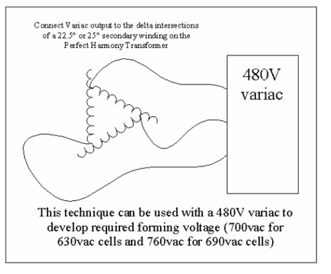
I attach the drawing showing the secondary terminals of the transformer so that you can say if possible, where exactly should the output of the variac be connected.
Thanks!
Hi Mfuachuma,
Please see the attached image for how to connect the variac to a transformer secondary winding. You will need to identify a secondary winding's delta intersections and connect the variac to them. If you need additional help upload a photo of the secondary side of your transformer and I can identify the delta intersections for you.
Regards,
will4
Will4!
Thank you so much! Very helpful this one. I have attached some pictures of the secondary side of the transformer as you asked.
Again, after the connection, is there anything to be done with regards to mode or parameter settings on the drive?
Regards,
Mfuachuma.
Hi Mfuachuma,
Please see attached sketch for the connection details. You will need to isolate the drive and then gain access to the transformer cubicle. Squeeze in between the right hand side of the transformer to gain access to the secondary connections on the back of the transformer itself. Connect the variac as shown in the attached sketch to the winding's closest to you. After connecting close up the drive and turn on the control power and get the blowers running. You dont need to change any parameters. Just wind up the voltage slowly at the appropriate rate. Once you reach sufficient volts the cell diagnostics will run. Remember that the input side of the transformer (Medium Voltage) will be live. You may need to disconnect your incoming supply cables if they are earthed at your switchboard.
Regards,
will4
Hi Will4,
Thank you so much! This was really helpful.
I managed to connect and performed the exercise successfully (largely). In one drive though once the cell diagnostics begin, I get some alarms like "cap share" and "blown power fuses". Surprisingly, once I check the fuses, they look OK.
I will proceed with troubleshooting today. In the meantime, if anyone has any idea to offer, please, it will be highly appreciated.
Thanks!
Hi Mfuachuma,
Most likely these faults are due to issues on the cell control boards. You can move the cell control boards between cells to see if the faults move with them. If they do the cell control boards will need to be exchanged. The faulty cell control boards can be repaired.
Regards,
will4
Thank you so much Will4!
I replaced the faulty cells and finally the reforming exercise was a success. I have powered the drive with MV and no fault so far ( over 48 hours).
Your help is highly appreciated!
Regards,
Mfuachuma.
Previous : SINAMICS PERFECT HARMONY GH180 GenI/GenII/GenIII/GenIV/6SR5, Power cell 260 A Debug Tools v 5.4.0.1-
Next : GH180 recommend drive running over 7 years to replace its electrolytic capacitors in the power cells


 Copy product links
 Long by picture save/share
INQUIRY


Add Successfully
We are the world's leading supplier of spare parts for medium voltage drives of various brands

点击右上角
分享给朋友吧
GET IN TOUCH

East Sun Industrial Centre, No 16 Shing Yip Street Kl, Hongkong

Call us : +852 5261 7322

Email us : [email protected]
SITEMAP
BUSINESS HOURS
Monday to Friday : 9 am to 6 pm
Saturday : 9 am to 12 am
Sunday : Closed Support Hours in 24/7 Everyday
DISCLAIMER:
We are not an authorized distributor, reseller or representative of the following products presented on this website. All Product names and logos throughout this site are trademarks of their respective holders. Use of them DOES NOT imply any affiliation with or endorsement by them.
© 2020 robiconperfectharmony.com site . All rights reserved Site Map
